
ACME Screws
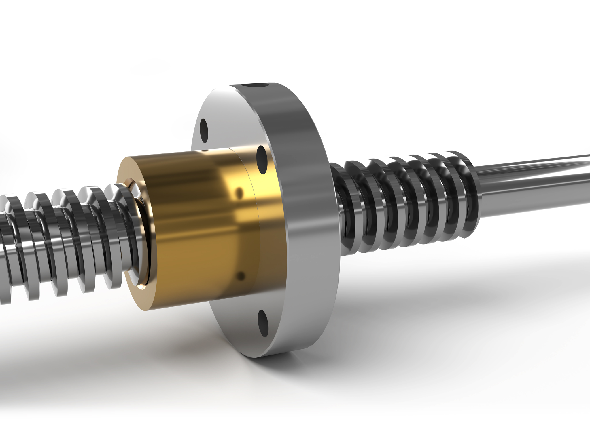
ACME screw products are typically less costly than a ball screw and more tolerant to less-than-optimal operating environments. Many ACME screws provide sliding element friction that prevents back driving, eliminating the need for a braking device to account for the stored energy within a system. Catalogued and non-catalogued ACME products are produced in a variety of sizes, thread types and materials.
Definitions & Formulas
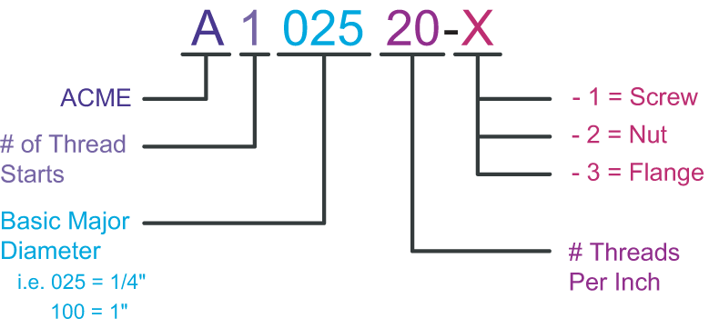
Nomenclature
The following describes the part number nomenclature for ordering ACME products:
Terminology
The following illustration visually depicts and augments the subsequent definitions:
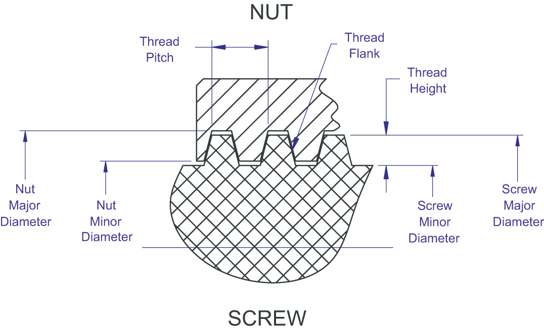
Major Diameter
The diameter described by a cylinder formed by the crests of the screw.
Minor Diameter
The diameter of a cylinder formed by the roots of the threads. Also known as the ROOT DIAMETER.
Pitch Diameter
The theoretical diameter described dimensionally by the mean value of the major and minor diameters.
Thread Height
Half the difference between the major and minor diameters. The basic thread height is equal to one half of the thread pitch. The basic thread height is also equal to the thread thickness at the pitch diameter.
Thread Lead
The nominal translational distance produced by one turn of the thread. The lead is equal to the SCREW PITCH x THE NUMBER OF STARTS. Therefore, the lead = pitch for single start threads.
Thread Pitch
Nominal distance between the same points on adjacent thread forms as measured parallel to the rotational axis. The pitch is equal to the SCREW LEAD / THE NUMBER OF STARTS.
Threads Per Inch
Equal to the reciprocal of the pitch.
Thread Starts
The number of uniquely independent threads contained either on the screw or the nut.
Thread Flank
The area of contact between the nut thread and the screw thread.
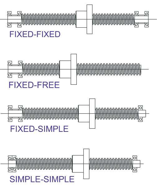
End Fixity
Four basic combinations of end fixity are commonly utilized. The fixity basically describes the bearing configuration being used to support the rotational axis of the screw. The four typical combinations of end fixity include: fixed free, both ends simple, one end fixed and the other end simple, and both ends fixed.
FREE = the free end does not support the rotational axis of the screw.
SIMPLE RADIAL = this end fixity only supports radial loads and not axial loads.
SIMPLE ANGULAR = this end fixity supports both radial loads and axial loads.
FIXED = this end fixity supports both radial loads and axial loads while distributing any moment loading over a greater distance and increasing the resultant column load strength and critical speed.
The following calculations assume a well lubricated screw and nut and also a clean operational environment. Substantial increases in driving torque can occur if lubricant is insufficient.
Applied Dynamic Loading
Each unique application needs to be evaluated such that ALL force components are realized and accounted for. The force components might include: weight of the sliding mechanism (if vertical), weight of the sliding mechanism multiplied by the coefficient of sliding friction (if horizontal), any direct forces resisting the linear motion (such as tool cutting loads), and any other applicable force components.
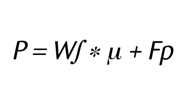
P = Applied Dynamic Load (LBS)
W∫ = Weight of Sliding Load (LBS)
µ = Coefficient of sliding friction
(=1 if load orientation is vertical)
Fp = Force component pushing directly against
the sliding mechanism
Screw RPM at Maximum Velocity Note: For below, Compare the calculated screw RPM to the critical speed value to determine if the below RPM is attainable.

Critical Speed
Critical Speed is the theoretical linear velocity (inches per min.) which excites the natural frequency of the screw. As the speed of the screw approaches the natural frequency (critical speed), the screw shaft begins to resonate which leads to excessive vibration. The resulting resonance can occur regardless of whether the screw or nut rotates or regardless of screw orientation. R/B/S recommends limiting the maximum linear velocity to 80% of the calculated critical speed value.
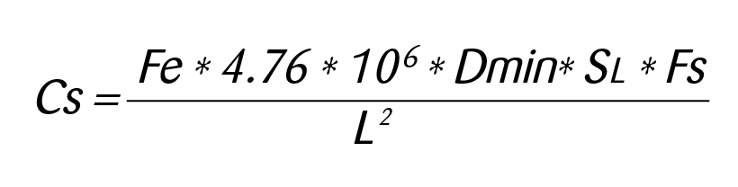
Cs = Critical Speed (Inches/min.)
Dmin = Minor Diameter (root) of Screw (In.)
SL = Screw Lead (In.)
L = Distance between bearing supports
Fe = End Fixity Variable
= .36 for Fixed-Free Support Configuration
= 1.00 for Simple-Simple Configuration
= 1.47 for Fixed-Simple Configuration
= 2.23 for Fixed-Fixed Configuration
Fs = Factor of Safety (80% recommended)
Column Load Strength
Column Load Strength is the ability of the screw shaft to withstand compressive forces. The fundamental limit occurs when a compressive load exceeds the elastic stability of the screw shaft. Exceeding the column load will result in bending and buckling of the screw. This mode of failure can only occur when the screw shaft is in compression and never in tension. R/B/S recommends limiting the maximum compressive load to 80% of the calculated column load strength.
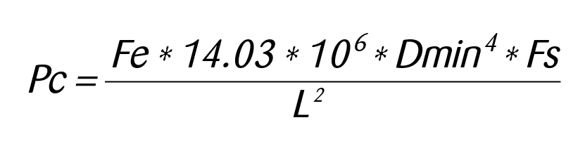
Pc = Maximum Column Load (lbs.)
Dmin = Minor Diameter (root) of Screw (In.)
L = Distance (max.) between load and bearing in compression (inches)
Fe = End Fixity Variable
= .25 for Fixed-Free Support Configuration
= 1.00 for Simple-Simple Configuration
= 2.00 for Fixed-Simple Configuration
= 4.00 for Fixed-Fixed Configuration
Fs = Factor of Safety (80% recommended)

Dmin = Minor Diameter of the Screw (inches)
L = Distance between Bearing Supports (inches)
Sr = Slenderness Ratio Limits for End Fixity
= 25 for One End Being Fixed and the Other End Being Free
= 50 for Both Ends Having Simple Supports
= 70 for One End Being Fixed and the Other End Being Simple
= 100 for Both Ends Having Fixed Supports
Torque for Motion at Constant Velocity
The equation below only determines the required torque to maintain a constant velocity for the applied load as reflected to the drive end of the screw. The peak system torque would need to account for all of the pertinent torque required to accelerate the load, the constant torque value, any mechanical gearing ratios, angular inertias, and other specific characteristics of each unique application. CONSULT FACTORY ENGINEERING FOR SPECIFIC APPLICATION CONCERNS.

Tcv = Torque required to move the load at constant velocity (Inch*pounds)
Pd = Force of total applied load (LBS)
SL = Screw Lead (Inches)
Eƒƒ = Forward Driving Efficiency