Inch Ball Screws
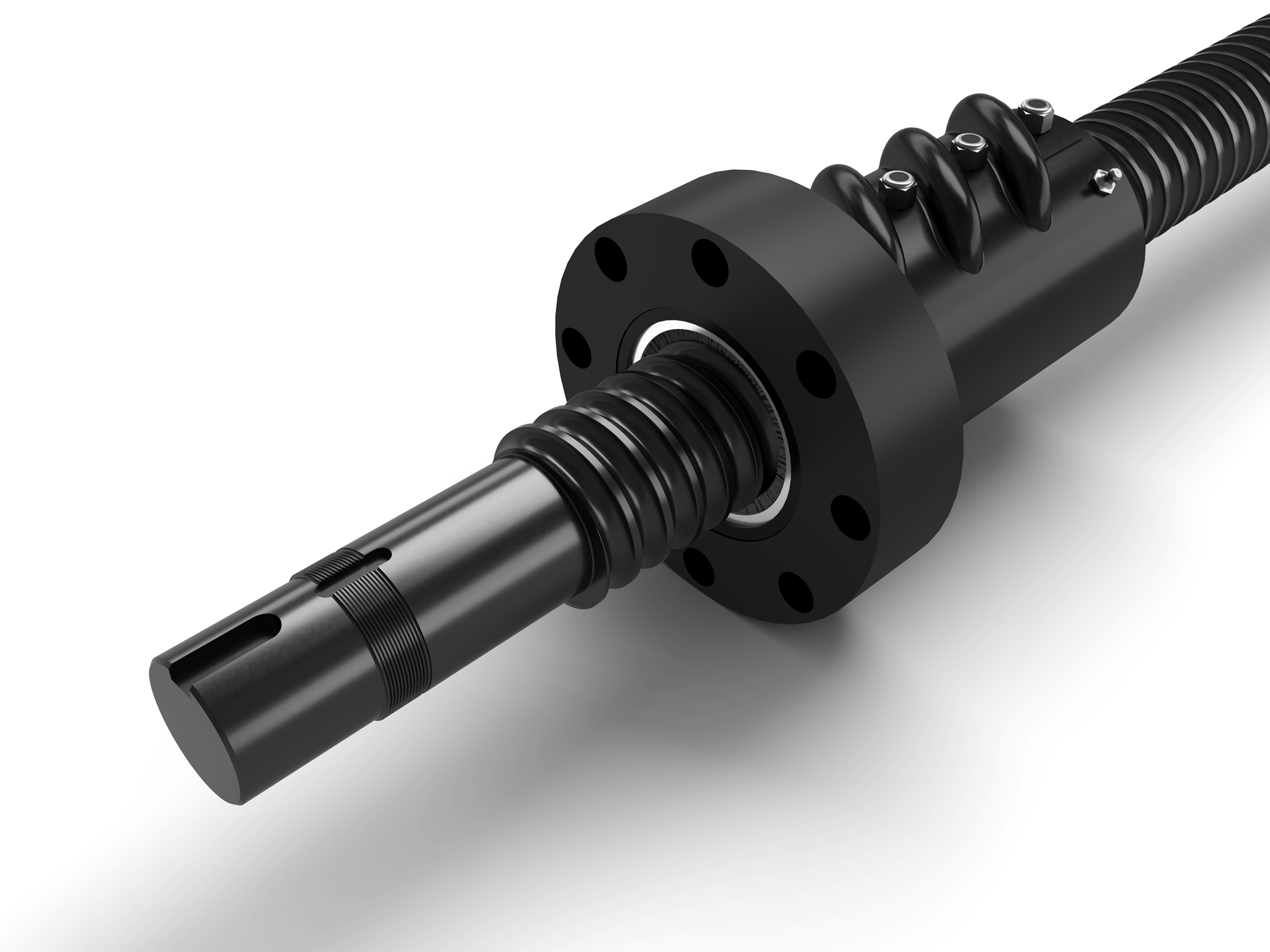
Our ball screw assembly consists of a screw and a nut, each with matching helical grooves The balls which roll between these grooves providing contact between the nut and the screw. These re-circulating bearings allow the unit to operate at an extremely high rate of efficiency with excellent static and dynamic load ratings..
We stock 56 ball screw models in a variety of materials and designs including high and low carbon alloy steels and various grades of stainless steel available in standard and metric sizes.
Our ball screws provide the linear motion solutions to a variety of industries including:
Building Construction, Heavy Lift, Transportation, Marine, Medical, Food Packaging, Energy
Definitions & Formulas
Screws
A ball bearing screw is just that: a screw which runs on ball bearings. The screw and nut have matching helical grooves or races, and the ball bearings recirculate in these races. There is no physical contact between the screw and the nut. As the screw or nut rotates, and the rolling balls reach the trailing end of the nut, they are deflected or guided from this “pitch” contact by means of a return tube and returned to the leading end of the circuit. There, the cycle resumes and the balls recirculate continuously.
Major Diameter
(Land Diameter) The outside diameter of the screw thread.
Minor Diameter
(Root Diameter) The diameter of the screw shaft as measured at the bottom of the ball thread track. This diameter is used in column load and critical speed calculations. Minor diameter also is a consideration in support bearing selection.
Ball Pitch Diameter
(Ball Circle Diameter) The theoretical cylinder passing through the center of the balls when they are in contact with the ball screw and ball nut races.
Lead
The axial distance the screw or nut travels in one revolution.
Lead Error
(Accuracy) The difference between the actual distance traveled compared to the theoretical travel based on the lead of the screw. The lead error for a standard screw will not exceed +/-.007” per foot and a premium grade screw will not exceed +/-.003” per foot. Lead error is cumulative based on the actual length of the ballscrew thread. Ref. Class 7-8 ANSI B5.48-1977. Lead charts describing incremental lead deviation offsets can be supplied (upon request). These incremental offsets can be input into motion controllers for lead error compensation.
Matched Leads
(Synchronous Screws) Used when multiple screws are being driven by a single drive in order to keep the screws in sync. Basically the lead errors are matched at the factory in order to minimize misalignments during the stroke. Consult factory for additional information on matched leads.
Pitch
The distance from one thread on the screw to a corresponding point on the next thread parallel to the screw axis. Pitch is equal to the lead on single start screws.
Screw Starts
The number of independent threads on the screw shaft. The lead of the screw is calculated by dividing the threads per inch by the number of starts.
Selective Fit
The process of selecting a unique ball size for reducing backlash to as little as .001 inches.
Materials and Hardness
Most screws and nuts are made from alloy steel and case hardened to Rc 56 minimum. Our stainless steel models are made of 17-4ph precipitation hardenable stainless steel with a surface hardness of Rc 38 minimum. Specialty materials can be supplied, contact factory.
Screw Straightness
Screw straightness is extremely important in minimizing screw vibration. Our ball screw stock is straight to .010” per foot not to exceed .025” over the entire length. We can hold straightness on machined screws to as little as .002”/foot (screw diameter and length dependent).
Temperature Range
Temperature range for our ball screws is between -65ºF. (-54ºC) and 300ºF. (149ºC) with suitable lubricants.
Lubrication
Lubrication is required to achieve optimum life for a ball screw assembly. Ball screws that are not lubricated can experience up to a 90% reduction in calculated life. In general, standard lubrication practices for anti-friction rolling element bearings apply. Grease, oil or dry film lubrication can be used. Many ball nuts are equipped with a 1/8-27NPT lube port machined into the nut body. For models that do not have a factory lube port, contact factory for recommendations regarding application of lubrication.
Ball Screw Finish
Ball Screw Finish is a black oxide coating to help prevent corrosion during shipping and brief storage. Long term corrosion resistance is accomplished by the rust inhibiting properties of the screw lubricant. In applications subject to extreme environments, additional coatings such as nickel, hard chrome, zinc or others can be applied. Contact Rockford Ball Screw for detailed specifications.
Preloading & Backlash
Backlash
The axial free motion between the nut and the screw. It determines the amount of lost motion between the nut and screw on a horizontal application. Backlash on standard nuts range from .005 to .015, depending on the size of the screw.
Selective Fit
The process of selecting a unique ball size for reducing backlash to as little as .001 inches.
Preloading
Method of eliminating backlash in a ball screw assembly. This is accomplished by the use of one group of ball grooves in opposition to another to eliminate backlash. Preloading increases stiffness (resistance to deflection) and provides for accurate positioning with very little increase in applied torque or decrease in load capacity.
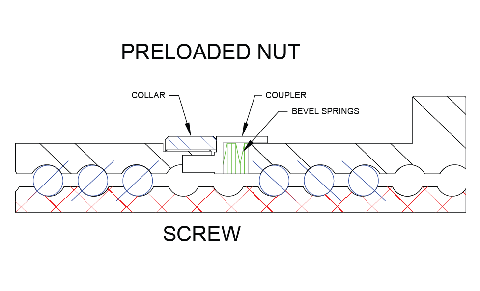
Rockford Ball Screw preloaded ball screw assemblies consist of two standard ball nuts joined by an adjustable preload package containing a collar, coupler and bevel or wave springs. The preload package has been designed to exert an axial separating force between the adjacent ball nuts thereby generating the requisite preload. Preloaded ball screw assemblies are required when positioning accuracy and repeatability must be maintained.
The adjustable preload can be set in a range between 10% (recommended) and 30% (maximum) of the dynamic load rating. While staying within this range, the assemblies demonstrate little loss of load carrying capacity or life.
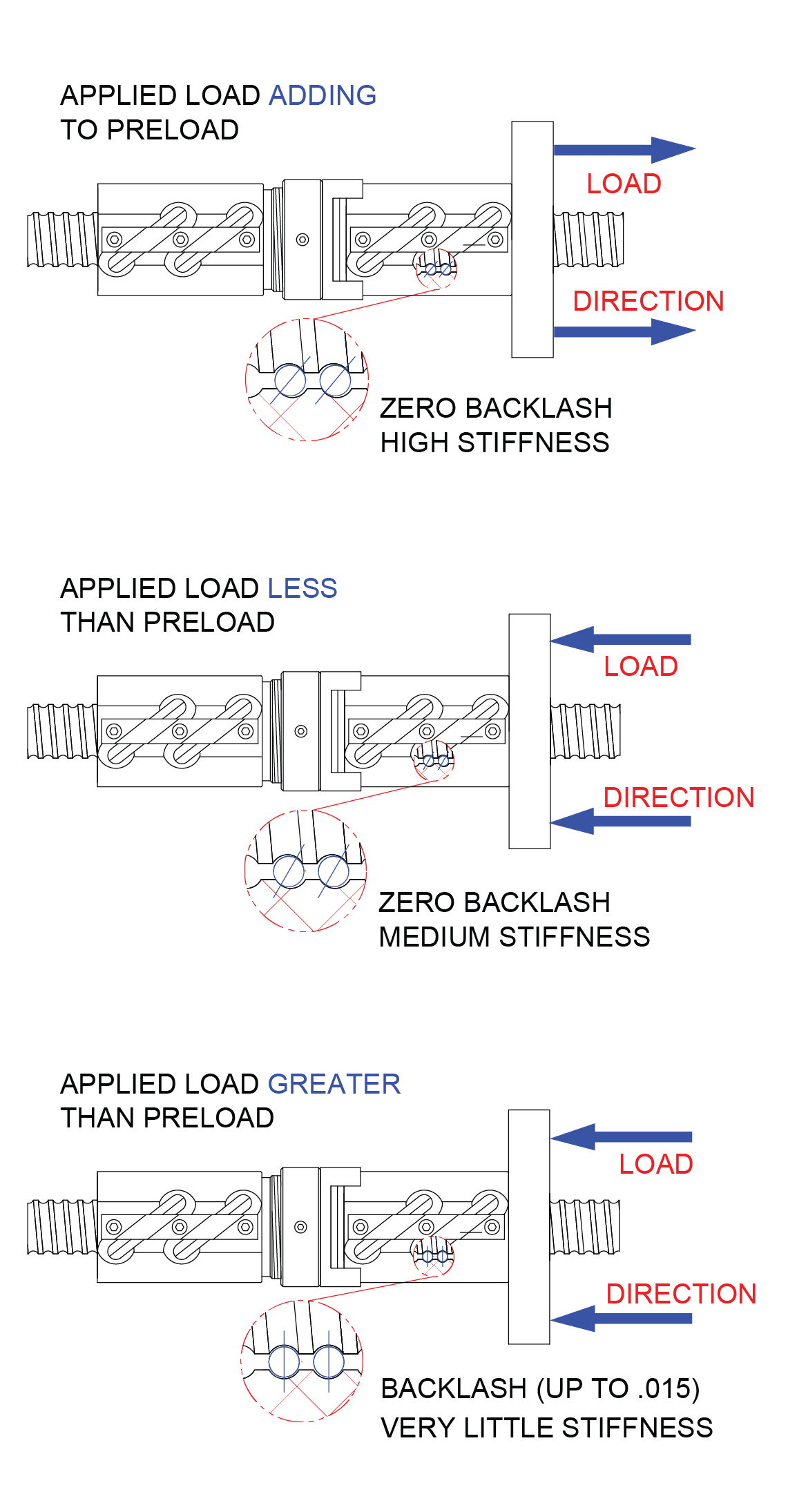
The three preload examples below illustrate the effects of load size and direction on preloaded units. The examples are important in selecting the size of preload and amount of preload force needed. The direction of loading effects ball screw stiffness and potential backlash.
Loading
Efficiency
Expressed as a percentage and is the ability of a ball screw assembly to convert torque to thrust with minimal mechanical loss. Rockford Ball Screws operate in excess of 90% efficiency.
Dynamic Load
The maximum thrust load under which a ball screw assembly will achieve a minimum of 1,000,000 inches of travel before first signs of fatigue are present.
Static Load
The maximum non-operating load capacity above which permanent damage of the ball track occurs.
Tension Load
A load that tends to stretch the ball screw. This is the preferred mode of attaching the load since column loading limitations would not effect the screw.
Compression Load
A load which would tend to compress or buckle the screw shaft. Use column load calculations to determine safe compression loads.
Axial Loading
The recommended method of attaching the load to the ballnut. This load should be parallel to the centerline of the screw shaft and equally distributed around the mounting surface.
Eccentric
(Moment Loading) A load tending to cock the ballnut on the screw and therefore reducing the rated life.
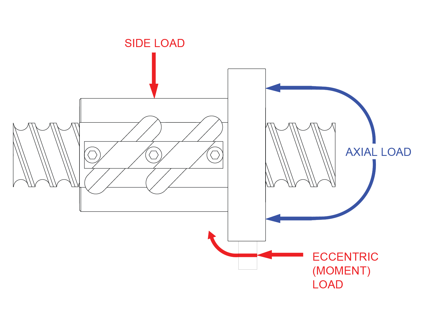
Side Loading (Radial Loading)
A load that is applied perpendicular to the screw shaft. This type of loading will also reduce the rated life of the ball screw assembly.
Ball Screw Life
(Life Expectancy) Expressed as total accumulated inches of travel under a constant rated thrust load (with proper lubrication and clean environment) before first evidence of fatigue develops (1,000,000 inches under stated rated loads). Ball screw life is rated similar to ball bearings (L10). The L10 life rating states that 90% of a similar group of screws will achieve this life. Although 10% will not achieve the life, 50% could exceed life by 5 times.
Applied Dynamic Loading
Each unique application needs to be evaluated such that ALL force components are realized and accounted for. The force components might include: weight of the sliding mechanism (if vertical), weight of the sliding mechanism multiplied by the coefficient of sliding friction (if horizontal), any direct forces resisting the linear motion (such as tool cutting loads), and any other applicable force components.
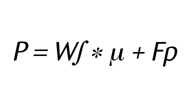
P = Applied Dynamic Load (LBS)
W∫ = Weight of Sliding Load (LBS)
µ = Coefficient of sliding friction
(=1 if load orientation is vertical)
Fp = Force component pushing directly against
the sliding mechanism
Coefficient of sliding friction for non-vertical loading applications
Steel on Steel ~.58
Steel on Steel (greased) ~.15
Aluminum on Steel ~.45
Gibb Ways ~.50
Dove Tail Slides ~.20
Linear Bearing (Ball Bushings) <.001
Frictional coefficients are included for reference purposes only and may vary in accordance with actual operating conditions.
Equivalent Load
This calculation is used in applications where the load is not constant throughout the entire stroke. This equivalent load can be used in life calculations. In cases where there is only minor variation in loading, use greatest load for conservative life calculation. Please note that the drive torques and horsepower requirements should always be based on the greatest thrust load encountered.
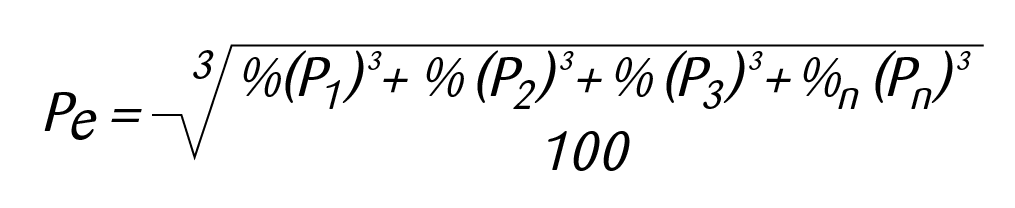
Pe = Equivalent Load (lbs)
Pn = Each Increment at Different Load (lbs)
%n = Percentage of stroke at load increment
Example:450 lb. load for 25% of stroke
760 lb. load for 50% of stroke
200 lb. load for 25% of stroke
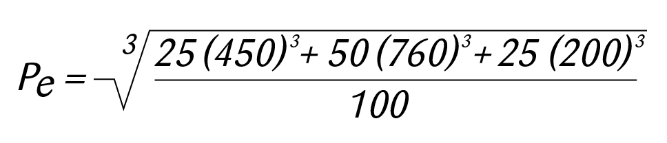
Equivalent Load (Pe) = 625 lbs.
Life At Loads
(Other than Rated) Based on the inverse cube ratio in that by operating at 1/2 the rated load you will get 8 times the life or operating at twice the rated load you will get 1/8 the life.

Design Life Objective
Design Life Objective is the number of inches that a ball screw will travel during the desired life of the machine. Generally it is ultimately stated in terms of years of life but we need to compare inches of travel to inches of calculated life.
Length of stroke = 6 inches
Cycle rate of machine = 20 Strokes/hr.
Hours of operation /day = 16 hours
Number of working days per year = 250 days
Number of years machine is designed for = 5 years
6 * 20 * 16 * 250 * 5 = 2,400,000 inches of life
Critical Speed & Column Loading
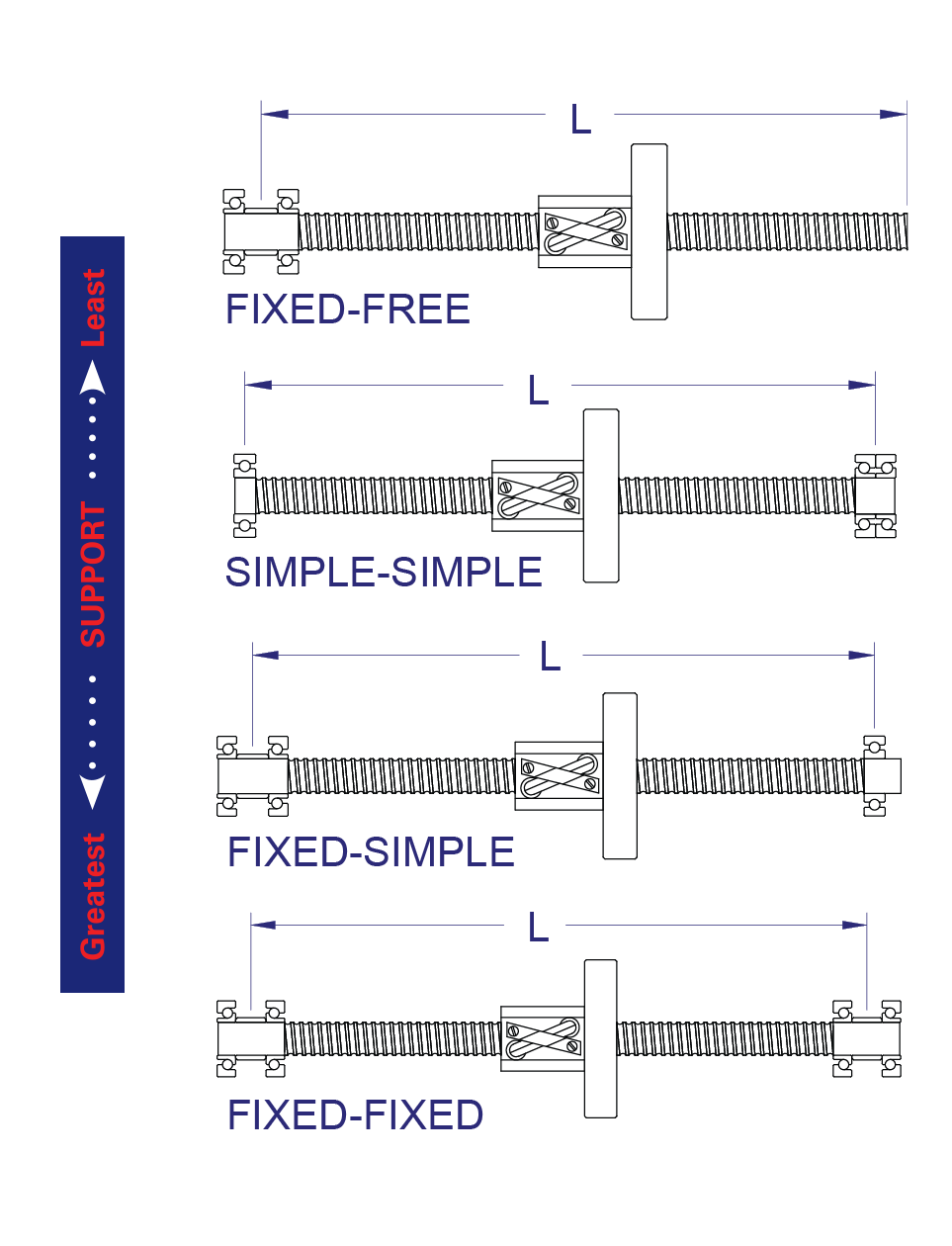
End Fixity
End Fixity (Bearing Mount Support Configuration) refers to the method by which the ends of the screws are supported. The end fixity basically describes the bearing configuration being used to support the rotational axis of the screw. The end fixity combinations are determined as a result of critical speed, column loading and system stiffness calculations. There are three basic end fixity styles that can be used in four combinations. The ends styles are "free" (no support), "Simple" (single point support), and "Fixed" (spaced support points).
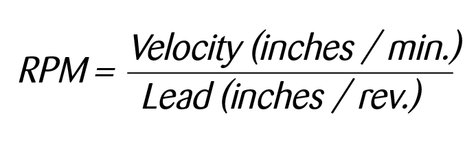
Critical Speed
Critical Speed is the theoretical linear velocity (inches per min.) which excites the natural frequency of the screw. As the speed of the screw approaches the natural frequency (critical speed), the screw shaft begins to resonate which leads to excessive vibration. The resulting resonance can occur regardless of whether the screw or nut rotates or regardless of screw orientation. R/B/S recommends limiting the maximum linear velocity to 80% of the calculated critical speed value.
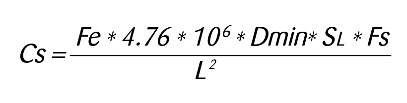
Cs = Critical Speed (Inches/min.)
Dmin = Minor Diameter (root) of Screw (In.)
SL = Screw Lead (In.)
L = Distance between bearing supports
Fe = End Fixity Variable
= .36 for Fixed-Free Support Configuration
= 1.00 for Simple-Simple Configuration
= 1.47 for Fixed-Simple Configuration
= 2.23 for Fixed-Fixed Configuration
Fs = Factor of Safety (80% recommended)
Critical Ball Speed (DN Value)
is the critical ball velocity within the ball nut. Exceeding this value can have a detrimental effect on the life of the ball screw assembly.
DN = (3000/Screw Nominal Diameter) * Lead (inches / revolution)
Column Load Strength
Column Load Strength is the ability of the screw shaft to withstand compressive forces. The fundamental limit occurs when a compressive load exceeds the elastic stability of the screw shaft. Exceeding the column load will result in bending and buckling of the screw. This mode of failure can only occur when the screw shaft is in compression and never in tension. R/B/S recommends limiting the maximum compressive load to 80% of the calculated column load strength.
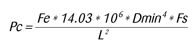
Pc = Maximum Column Load (lbs.)
Dmin = Minor Diameter (root) of Screw (In.)
L = Distance (max.) between load and bearing in compression (inches)
Fe = End Fixity Variable
= .25 for Fixed-Free Support Configuration
= 1.00 for Simple-Simple Configuration
= 2.00 for Fixed-Simple Configuration
= 4.00 for Fixed-Fixed Configuration
Fs = Factor of Safety (80% recommended)
Torque & Power Requirements
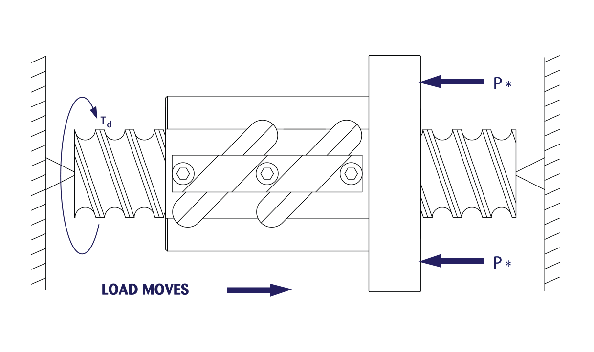
Drive Torque
Drive Torque is the amount of torque (inch pound) required by the ball screw to move the load. This torque does not take into account any inertial loading required for acceleration.
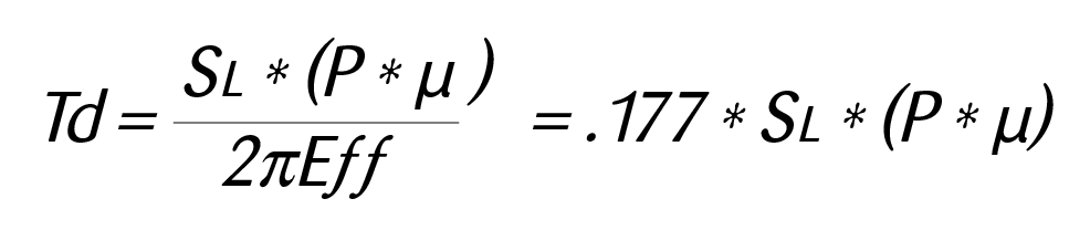
Td = Drive Torque (Inch pounds)
P = Applied Dynamic Load (LBS)
SL = Lead of Screw (Inches)
µ = Coefficient of Sliding Friction
(=1 if load orientation is vertical)
Eƒƒ = Ball Screw Efficiency (90%)
Coefficient of sliding friction for
non-vertical loading applications
Steel on Steel ~.58
Steel on Steel (greased) ~.15
Aluminum on Steel ~.45
Gibb Ways ~.50
Dove Tail Slides ~.20
Linear Bearing (Ball Bushings) <.001
Frictional coefficients are included for reference purposes only and may vary in accordance with actual operating conditions
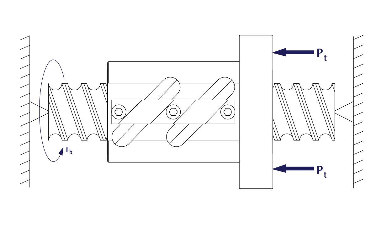
Back Drive Torque
The torque produced through the screw shaft by a thrust load on the ball nut. Ball screws can coast or backdrive due to the high efficiency of the mechanism (90%). If back driving is not acceptable, a method to resist the overturning backdriving systemic torque, such as a brake, will be required to hold the load. If backdriving is desired, the lead of the screw should be at least 1/3 of the screw diameter. Ideally the lead should be equal to the screw diameter. This calculated torque is the minimum amount of braking torque to hold the load in position.
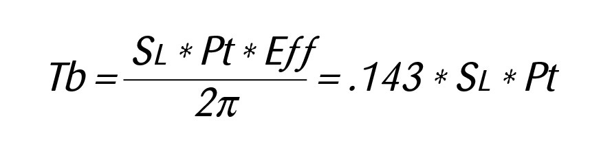
Tb = Backdrive Torque (Inch pounds)
Pt = Thrust Load applied to Nut (LBS)
SL = Lead of Screw (Inches)
Eƒƒ = Ball Screw Efficiency (90%)
Preload Torque
The additional torque required to overcome the frictional components of the preload force. This additional torque (inch pounds) needs to be added to the drive torque in order to calculate the required torque for constant velocity.
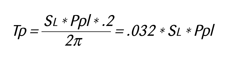
Tp = Preload Torque (Inch pounds)
Ppl = Preload Setting (LBS)
SL = Lead of Screw (Inches)
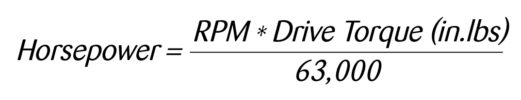
Power Requirements
The power (HP) to drive a ball screw assembly is a function of required drive torque and motor R.P.M. Horsepower should be calculated based on the maximum torque required during the stroke or cycle. The highest torques generally are during acceleration due to inertial loading.
Accessories
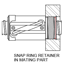
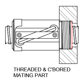
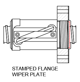
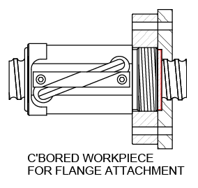
Wiper Kits
Wiper kits are available for all standard ball screw models. The nylon brush wiper is designed to keep large particulates from entering the ball nut. However for harsh environments, the use of boots or bellows to enclose the screw is recommended. Contact Rockford Ball Screw for further information on enclosures.
Our product pages detail the type of wiper mounting arrangement for each ball nut model. Brush wipers may require customer supplied retention primarily on the V-thread end of the ball nut (on models that do not have internal wipers and snap rings). A stamped flange retainer is available for many models that do not have internal snap rings for wiper retention (see data pages for available sizes).
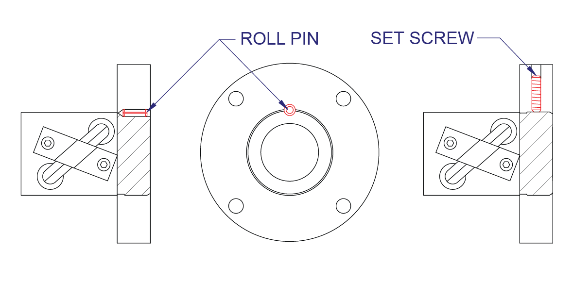
Mounting Flanges
If a mounting flange is used instead of the standard v-thread on the ball nut body, it must be permanently attached to prevent disengagement during operation. The two standard methods of retaining the flange is pinning and retaining with a set screw. Commercial thread locking adhesives may also be used (light loads only). It is always recommended that the flange pinning be performed at the factory to assure no metal chips are present after drilling.
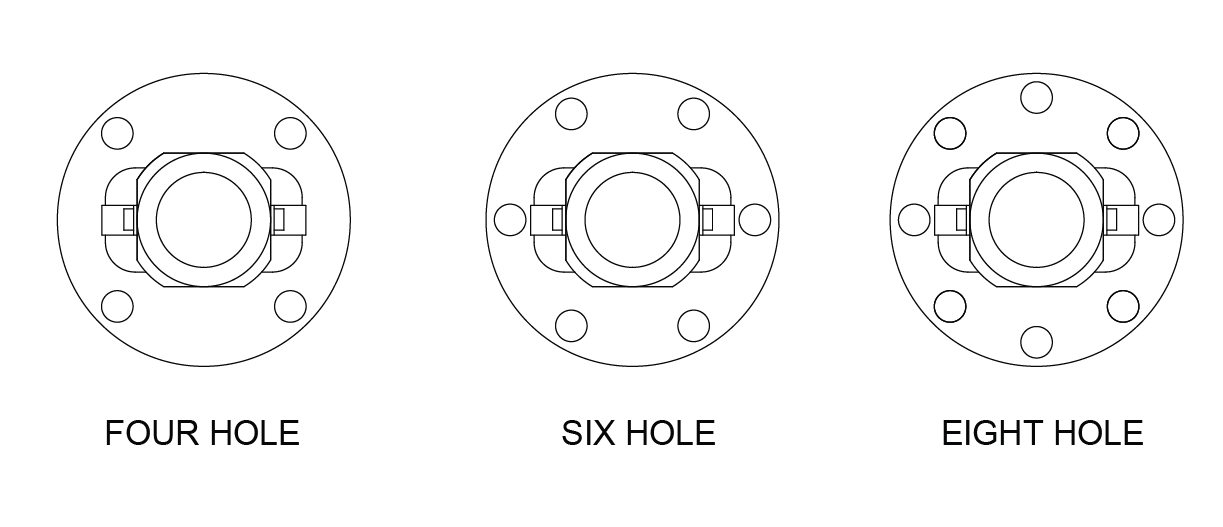
Flange Orientation
The orientation of the flange bolt holes to the return tube components varies with the number of holes in the flange. Unless otherwise specified, the following illustrations represent the standard orientations.
Safety Springs
The safety spring is a coiled spring installed in the inactive part of the ball nut and conforms to the ball screw thread. The spring is inactive during normal operation and does not contact the screw. In the rare event that the balls are lost from the ball nut, the safety spring will assume the load and prevent the nut from “free falling” down the screw. The spring is not designed to maintain normal operation and the ball screw assembly should be taken out of service after first engagement of spring. Safety springs are available for all ball screw models. The safety spring is mandatory if the screw is being used to lift, support or otherwise transport people. Please inform our customer representative that you require the safety spring for your particular application.
Free Wheeling
Free Wheeling Ball Screws
In addition to our full line of recirculating ball screws, we also offer a free-wheeling ball screw assembly (pages 70-73). The free wheeling screw (also referred to as planetary or epicyclic ball screws) is different from a standard ball screw in that it utilizes a ball cage (retainer) inside the nut. As the cage contacts the stop pins in the screw at the ends of the stroke, the ball nut will stop linear movement but the screw will continue to rotate (free-wheel). When the screw rotation reverses, linear motion occurs away from the stop pin and will travel until the cage contacts the pin at the other end of the stroke.
The advantage of the free wheeling screw is that limit switches or other types of stops are not necessary. This eliminates the possibility of over travel which can cause problems with many applications. The controlled stroke feature is used in many applications such as bed or chair actuations, trim tab actuators and electrical switching devices.
The free wheeling screw operates with the same efficiency (>90%) as a standard ball screw. Due to the planetary slipping of the nut in relation to the screw, there is an effective lead that is different than the actual lead of the screw. The effective lead is always less than the actual lead and varies with the direction and magnitude of the load (see pages 70-73). Since the lead is a variable, this device is not recommended for applications that rely on rotation of the screw for position feedback.
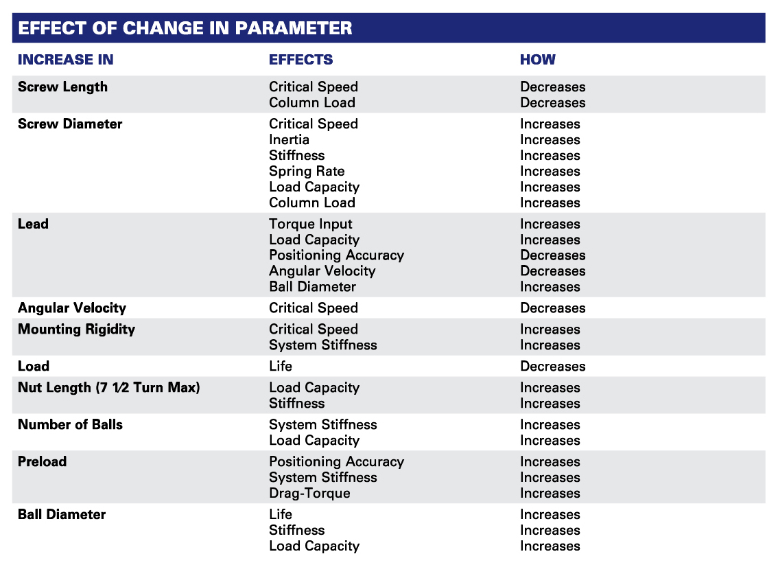
Effect of Change in Parameter