
Sizing & Selection
Our rail and bearing blocks come together to solve endless engineering challenges across numerous industries and applications. Therefore, sizing and selecting an assembly or linear guide system should be a careful and systematic process. Below you will find step-by-step instructions to guide you through the sizing and selection. If, at any time, you need to speak with our team, fill out the Quick Contact form to the right, or visit the Customer Support section of the website.
SIZING & SELECTION PROCESS
Initial Design Considerations
The following design considerations are a representation of the information that is typically defined prior to performing the selection calculations. For this example, Given Specifications will be shown in Green, Calculation Results will be shown in Blue, and Catalog Product Data will be shown in Red. Given Specifications- The device duty cycle parameters are as follows:
- a. Gross device cycle time = 30 seconds
- b. Time allocated for extending the device = 4.0 seconds
- c. Time allocated for retracting the device = 4.0 seconds
- d. Operating at 24 hours per day, 260 days per year, and at 85% efficiency (uptime) for 10 years
- e. Each cycle consists of 2 travels; one extend and one retract stroke
- Linear device travel for extending and retracting motions = 1335 mm respectively. The initial point of displacement = 0.
- The orientation of the device will be horizontal and preferably bolted through the top of the block.
- The application will have very little impact, vibration, or moment loading.
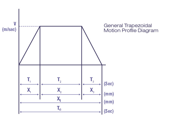
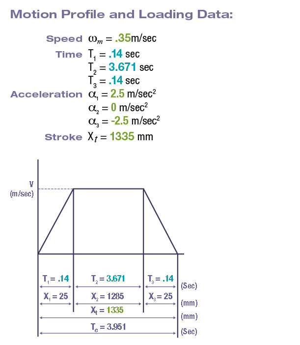
- The motion profile will be trapezoidal (Fig. 19) and have equivalent acceleration and deceleration rates as shown below:
- a. Acceleration a1 = 2.5 meters /sec2
- b. Deceleration a3 = -2.5 meters/sec2
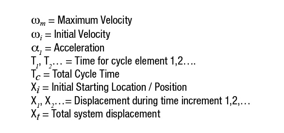
- c. Maximum Velocity(wm ) = .35 meters/sec
- d. The initial velocity wi = 0
Step 1
Calculate the Required Service Life Based on the Design Considerations.
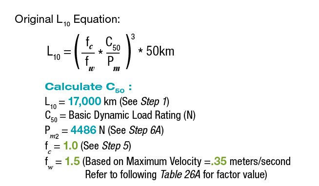
By definition, the service or L10 life is the amount of travel required during the expected life of the system. The information shown in items 1 and 2 of the given specifications above will be used to calculate the service life requirement. The results from this calculation will be used in Step 7A.
1335 mm per travel*2 travels per cycle*2 cycles per minute*60 minutes per hour*24 hours per day*260 days per year*10 years of L10 life*85% efficiency/ 106mm/km = 16,994 Km.
According to the calculation above, service life will be evaluated based on 17,000 Km of travel (This value has been rounded from 16,994 to 17,000).
Step 2
Calculate the Extend, Retract, and Total Cycle Time based on Acceleration, Deceleration, and Maximum Velocity.
The extend, retract, and total cycle time will be calculated based on the information listed in item 5 of the given specifications. The total calculated cycle time will be evaluated to ensure conformity to the 4.0 second design objective. Additionally, it will be necessary to determine the validity of the specified acceleration rates as they will be used in Step 3 to determine the dynamic block loading.
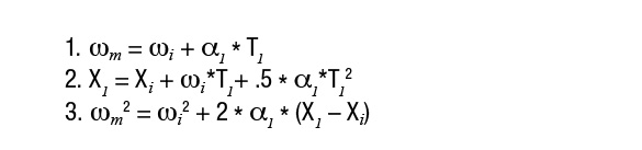
2A - The following linear motion variables and equations will be utilized:
Uniform Rectilinear Motion Equations:
Uniform rectilinear motion requires that the acceleration = 0 and the velocity = constant.
Uniformly Accelerated Rectilinear Motion Equations:
In uniformly accelerated rectilinear motion, the acceleration = constant and the velocity = variable
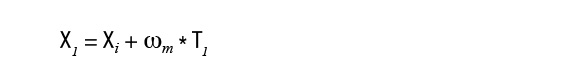
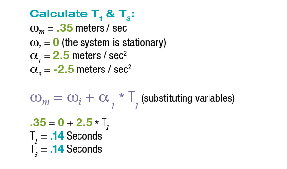
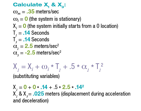
2B Solve for T1, T3, X1 and X3 during the initial acceleration and final deceleration of the motion profile:
Using the equations above and the information in item 5 of the given specifications, the time increment T1 and the displacement X1 will be solved. Given that the acceleration and deceleration rates are equivalent, the time increment T3 will equal T1 and the displacement X3 will equal X1. (See previous motion profile diagram for T1, T3, X1, & X3). The results from these calculations will be used in Steps 2C and 2D.
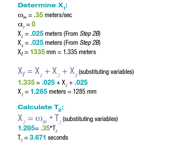
2C - Solve for T2 which occurs during the period of constant velocity for the motion profile:
The initial calculation will determine the displacement required (X2) once the system has reached maximum velocity. Once the displacement required for period T2 has been determined, the time required for the displaced distance will be solved. The information shown in items 2 and 5 of the given specifications, as well as the results from Step 2B will be used to perform these calculations.
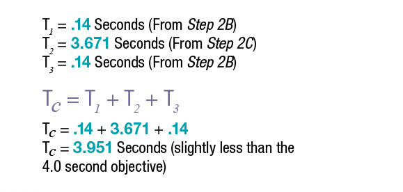
2D - Solve for the Total Calculated Cycle Time:
The total cycle time will be the summation of the time periods T1, T2, and T3.
2E - Design Concept & Loading Calculations:
The purpose of the following section is to populate the motion profile diagram with the values previously calculated above in Step 2 and establish an initial geometric design concept. This concept will be utilized as the basis for calculating the applied loading to each guide block.
Step 3
Calculate Individual Applied Block Loads.
In this step, the applied loads will be evaluated for the periods of acceleration and constant velocity. These subsequent equations will calculate loading in both the normal and transverse directions.
Note: In general, linear motion system applications should always be evaluated with respect to the highest loaded block as it will be the first to reach the calculated design life limit.
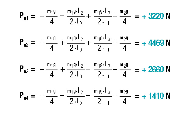
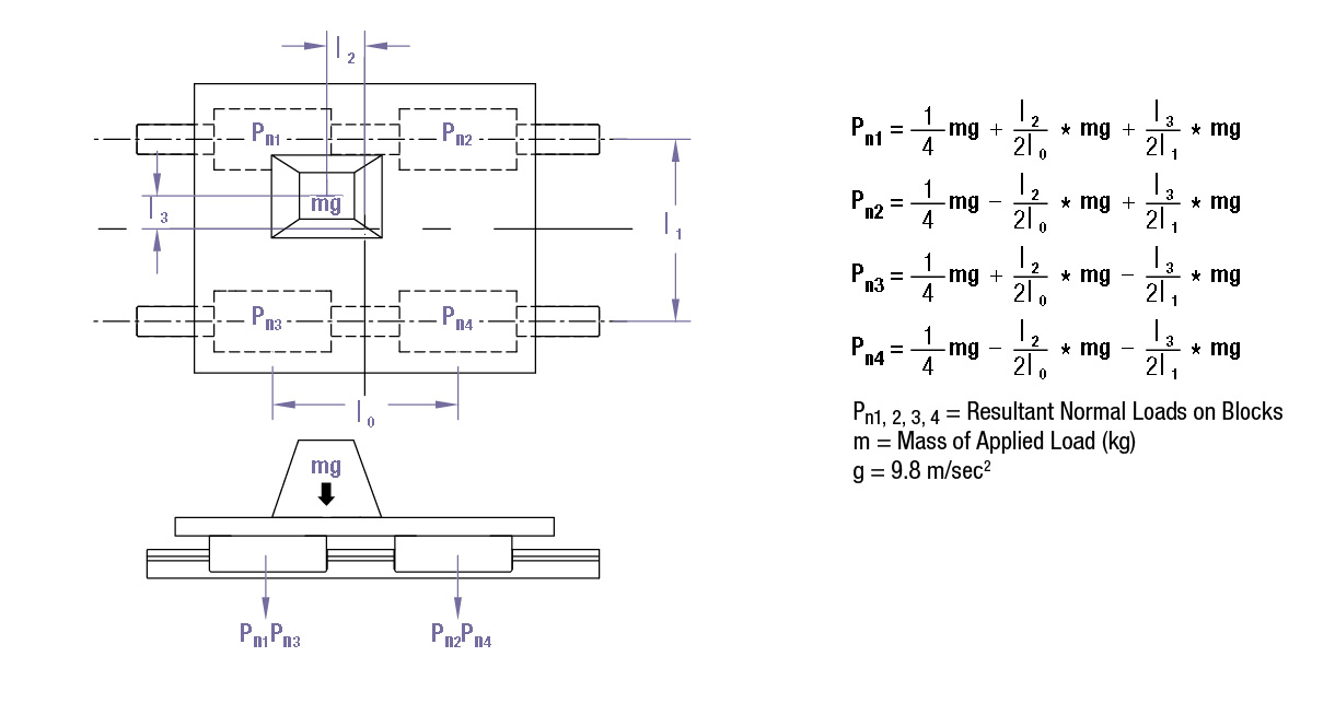
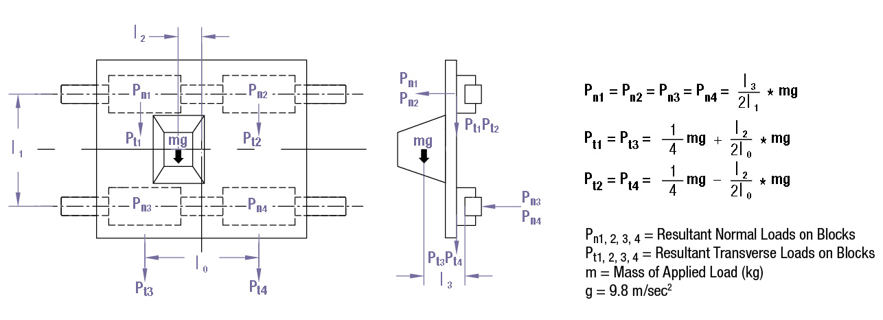
3A - Load During Constant Velocity:
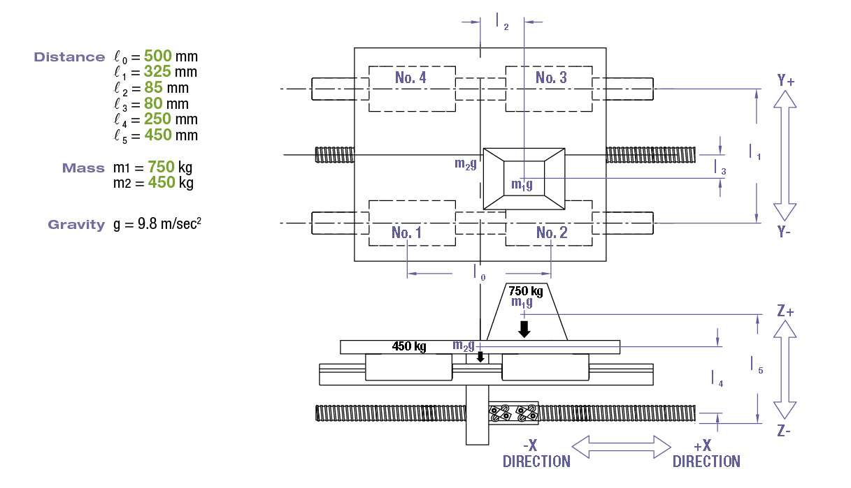
Applied Load in the normal direction Pn
(Use the information in diagram above for the equations in Steps 3A-3E)
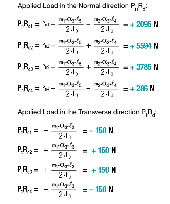
3B - Load During X- Acceleration:
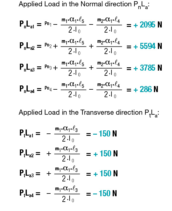
3C - Load During X- Deceleration:
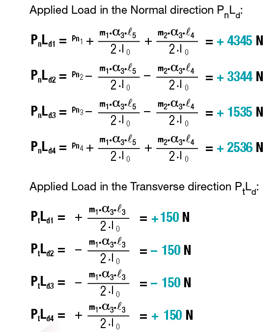
3D - Load During X+ Acceleration:
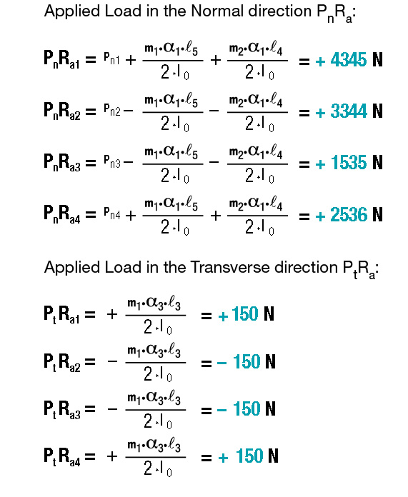
3E - Load During X+ Acceleration:
Step 4
Calculate the Equivalent Block Loads.
The individual equivalent block loads (also referred to as resultant load) are calculated by summing the absolute value of the normal and transverse loads applied to each block. The values used in the following equations were previously calculated in Step 3. The determined equivalent load values will then be used in the successive Mean Load Calculation (See Step 6).
4A - Equivalent Load Calculation:
Use the values from Steps 3A-3E for these equations.

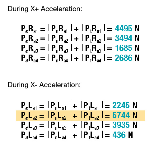
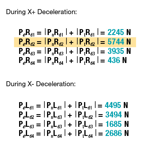
According to these calculations, Block #2 has the highest maximum applied load of 5744 N during acceleration in the X- direction and deceleration in the X+ direction. This information will be used in Step 5.
Step 5
Evaluate Static Loading.
NOTE: The L10 Fatigue Life and Static Loading should be evaluated for each application to ensure proper product sizing.
Each variable in the following Static Loading equation will be isolated and quantified. The objective will be to calculate the minimum allowable Basic Static Load Rating (C0 ).
Rearrange Equation, Substitute Values, and Calculate to solve for Basic Static load Rating (C0):
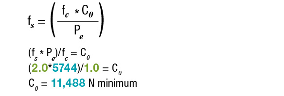
The product selection will need to have a minimum Basic Static Load Rating (C0 ) of 11,488 N
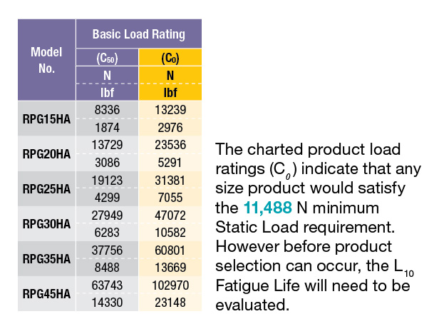
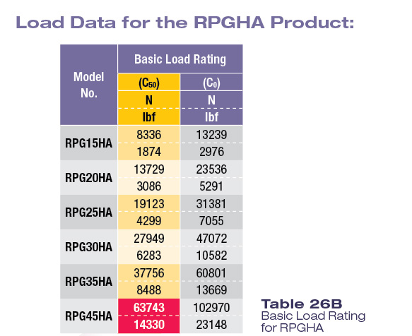
Load Data for the RPG-HA Product:
Step 6
Evaluate Fatigue Life (L10) and Select Product.
The main objective of this section will be to evaluate the effects of dynamic loading on product selection. Initially, this evaluation will begin by solving the Mean Load applied to each block. The Mean Load and other input factors will then be used to solve for the minimum required Dynamic Load Rating (C50 ). At the end of this section, the appropriate product selection will be achieved based on the full scope of this application example.
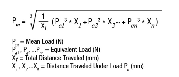
Mean Load (Pm) Equation for cycles with Stepwise Load variation:
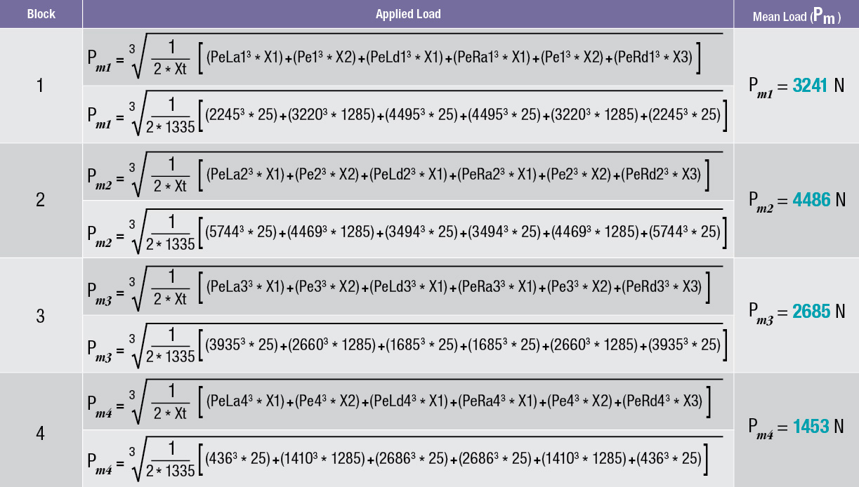
Calculate Applied Mean Load (Pm ) per Block:
During the majority of all motion profile cycles, the resultant loading will vary as the system moves from point to point. These loads may vary for reasons such as mass acceleration (inertia), varying rates of acceleration, externally encountered forces, incrementally applied loads, or as a result of other factors. The following Mean Load Calculation transforms these varying cycle loads into a corresponding load of constant value. The block determined to have the maximum applied Mean Load will be the focus as it will have the shortest Fatigue Life (L10).
NOTE: The previously calculated equivalent applied load values will be used to calculate the Mean Load.
6A - Solve for the Individual Mean Applied Load Per Block:
Step 7
Determine the Dynamic Load Rating (C50) and Select Product.
The Required Dynamic Load Rating (C50) will be assessed for the block with the greatest Mean Load. This block theoretically will have the shortest Fatigue Life and will uniquely indicate the product selection. In this application example, Block 2 has the greatest calculated Mean Load of 4486 N.
NOTE: In general, linear motion system applications should always be evaluated with respect to the highest loaded block.
7A - Solve for Minimum Required Dynamic Load Rating (C50):
The L10 life calculation, as found below, will be rearranged to solve for the Required Dynamic Load Rating variable (C50).
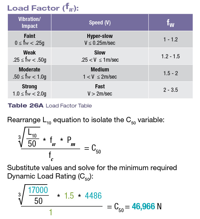
7B - Select product based on the calculated Minimum Required Dynamic Load Rating (C50):
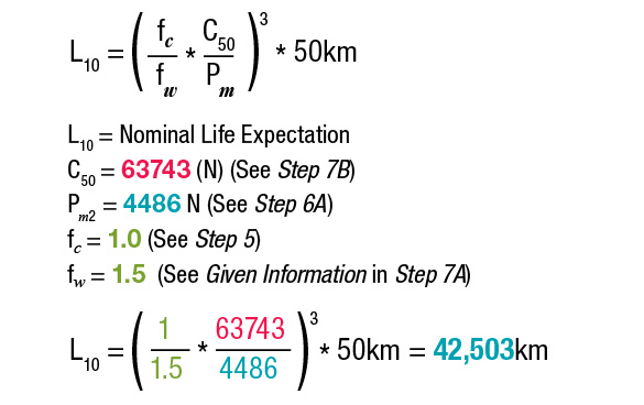
Based on the previously calculated minimum C50 value of 46,966 Newtons (Step 7A) and the stated design consideration to use a RPG-HA style block, the RPG45HA is the only available size that would satisfy the minimum Dynamic Load Rating requirement. (Refer to the chart below for product selection)
7C - Solve for the L10 life expectation (based on the RPG45HA product):
7D - Re-evaluate the selected size for Static Safety Factor (fs):
The static safety factor will be evaluated based on selecting the RPG45HA product.
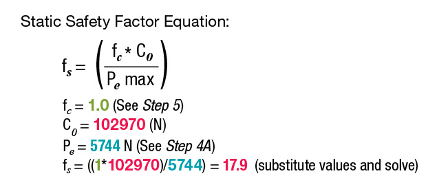
The calculated Static Safety Factor (fs) certainly exceeds the value necessary for the application. Therefore, the RPG45HA model is a viable selection choice.
Step 8
Alternative Solution for the Application.
As the design drawings were being created, the designer realized that the 45 mm product selection was too large for the machine envelope. As a contingency plan, the designer considers using the style RPGH-AL blocks which are a longer, higher capacity version of the
“A” style blocks.
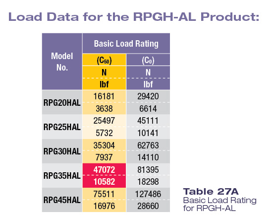
8A - Reference Load Rating Data for the RPGH-AL Blocks:
Referring back to the previously calculated minimum Required Dynamic Load Rating (C50 ) of 46,966 Newtons, the RPG35H-AL product is selected. It is determined that this product not only meets the minimum stated Required Dynamic Load Rating (C50 ) but also will fit within the work envelope.
8B - Solve for the L10 life expectation based on the RPG35HAL product:
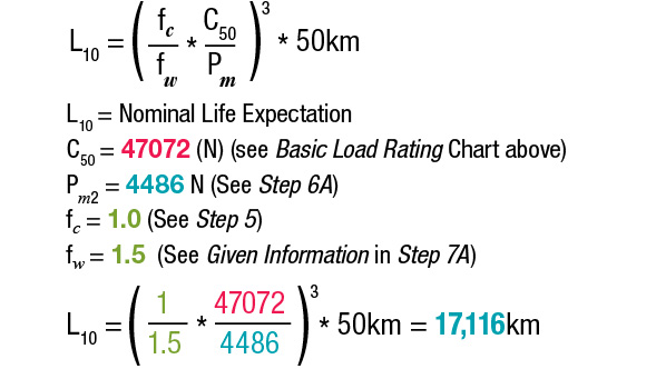
The RPG35HAL meets the Fatigue Life requirements (L10) that were calculated in Step 1 and is appropriate to use for this application.
Basic Dynamic Load Rating C50
The Basic Dynamic Load Rating C50 is used to calculate the Fatigue/Service Life of a linear guide system that is in motion and under load. The Dynamic Load Rating is defined as a load of constant magnitude applied in a downward direction to the center of the guide block which theoretically furnishes 50km of L10 life.
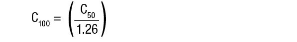
The following formula may be used to convert the Basic Dynamic Load Rating C50 to an equivalent Dynamic Load Rating for 100km of Rated Fatigue Life C100:
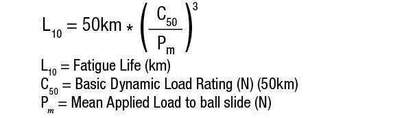
Fatigue Life (Service Life) L10
Fatigue Life (L10) is the total linear distance of travel displaced without incidental high cycle metal fatigue (flaking) by 90% of identical linear motion systems operating independently under the same conditions. This life calculation is also referred to as Service Life or Normal Life.
For linear guide systems utilizing balls as the rolling element, the fatigue service life can be calculated using the following formula:
Basic Static Load Rating C0
The Basic Static Load Rating is defined as the maximum allowable Static Load which can be applied in a downward direction to the center of the guide block. The application of loads in the excess of the Basic Static Load Rating will exceed the elastic properties of the material and yield permanent deformation. The resulting sum of the ball and raceway deformations is theoretically equivalent to .0001 times the diameter of the rolling element.
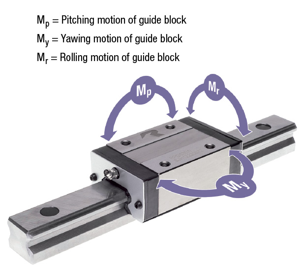
Basic Static Moment Load Rating M0
The Basic Static Moment Load Rating defines the magnitude of a moment which applied about one of three axes of freedom will yield the same degree of permanent raceway and bearing ball deformation as referred to in the Basic Static Load Rating C0.
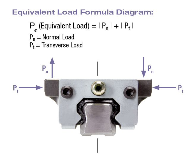
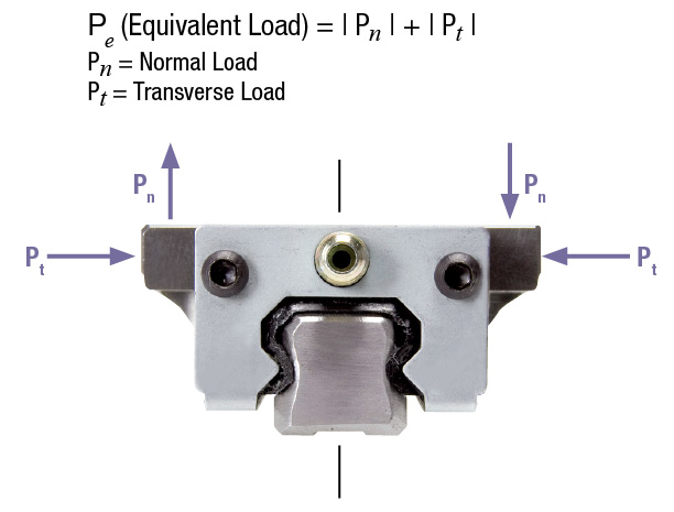
Equivalent Load Pe
When two or more loads are applied simultaneously from different directions (Normal loads and Transverse loads), a combined equivalent load, Pe should be calculated as shown below. This calculated equivalent load should be used in evaluating systemic L10 Service Life and Design Safety Factor (fs ).
Mean (Average Loads) Pm
The Mean Load is characterized as a load of constant value that results in a quantity of work equivalent to that of the original application. The Mean Load should be utilized in evaluating the Fatigue/Service Life (L10 ) of an application given the assumption that instantaneous peak loads do not exceed the Static Load Rating (C0 ) of the product. The remainder of this section will describe and address several typical Mean Loading conditions.
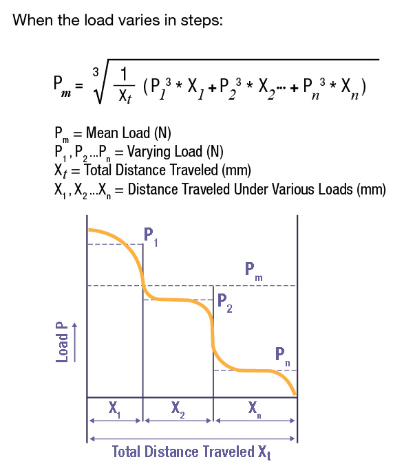
Mean Load calculations are used when the loading of systems and individual blocks varies as the system moves from point to point in an application. In general terms, the majority of loading profiles fall into one of three categories: Stepwise Loading, Linear Loading and Sinusoidal Loading. Each case presents a unique Mean Load calculation method as depicted in the following diagrams and specified in the associated equations.
Stepwise Loading
The system load increases (or decreases) in predictable plateaus over distances traveled. (Example: way covers collapsing)
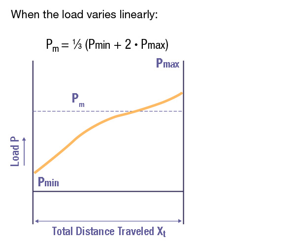
Linear Loading
The system load increases (or decreases) in direct proportion to the distance traveled.(Example: compressing a spring)
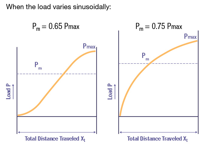
Sinusoidal Loading
The system load increases (or decreases) slowly at the beginning of travel, increases (or decreases) very rapidly in the center portion of travel, and increases (or decreases) at the rate equal to that at the beginning of travel at the end of the stroke. (Example: compressing a column of air)
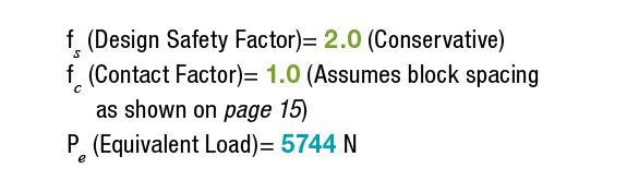
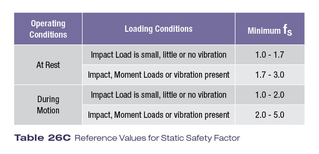
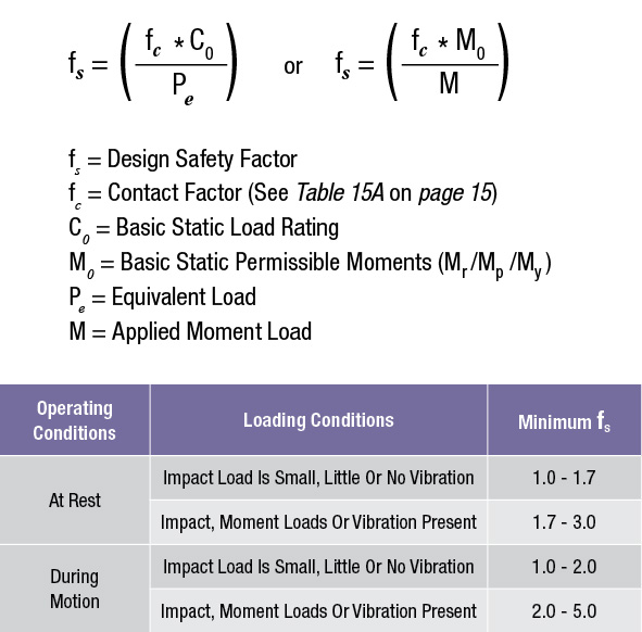
Design Safety Factor fs
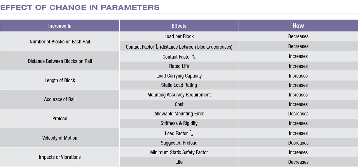
Design Safety Factor is used to account for peak acceleration/deceleration loads caused by vibrations, impacts, or inertial forces.
Design Safety Factor (fs ) represents the ratio of either the Basic Static Load Rating (C0 ) or Basic Static Moment Load Rating (M0 ) to the actual applied system load or moment.
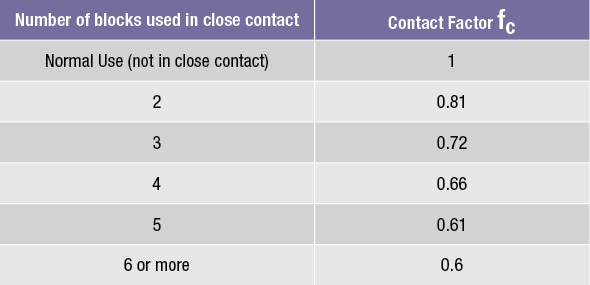
Contact Factor fc
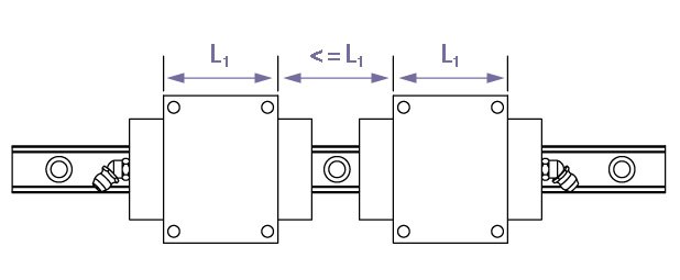
When multiple blocks are used on the same rail in close proximity to one another, uniform load distribution is difficult to achieve due to mounting surface errors, moment loading and other factors.
As a general rule, adjacent blocks are in close proximity when the space between adjacent blocks on the same rail is less than or equal to the L1 dimension of a given block. Refer to the chart and illustration below for applicable close contact factors.
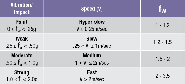
Load Factor fw
When vibrations and/or impacts are present during a reciprocating movement, the instantaneous loads can be difficult to fully quantify. In these instances, a load contact factor fw should be used.
Temperature & Hardness Rating/Factors
RPG linear guides will operate with no loss of efficiency or degredation in load carrying capacity up to 80˚ C (176˚ F). Under these conditions, a temperature adjustment factor will not be necessary. If the ambient temperature exceeds 80˚ C (176˚ F), please consult factory for further assistance.
Life Calculation
In applications where it is difficult to fully quantify all loads and/or peak acceleration/deceleration loading acting on a linear guide system, the L10 life should be calculated using the following formula:
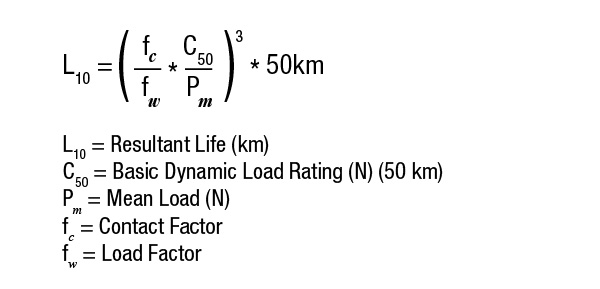
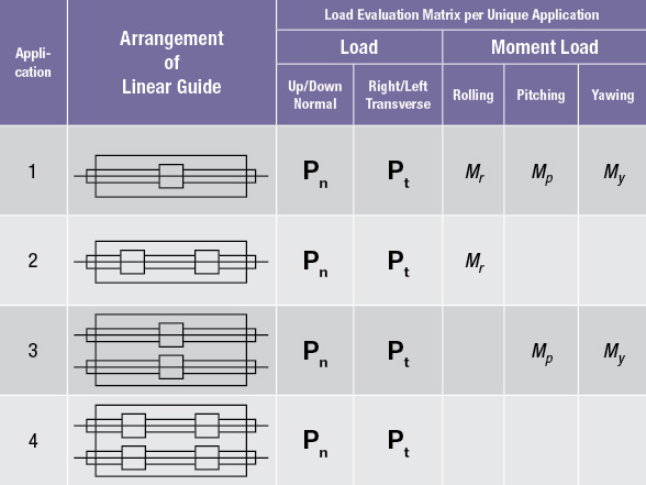
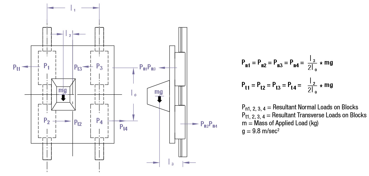
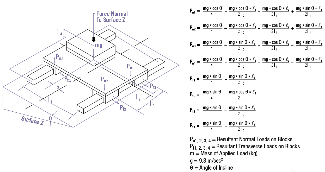
The loads acting on the a linear guide system vary according to the location of the center of gravity, the thrust, the load position, the moment loading due to acceleration and deceleration, the cutting forces and other external forces.
Below are some common guide system arrangements, please contact the factory if your application is not shown.
Horizontal Orientation
Perpendicular Orientation (Wall Mount)
Vertical Orientation
Angled Orientation
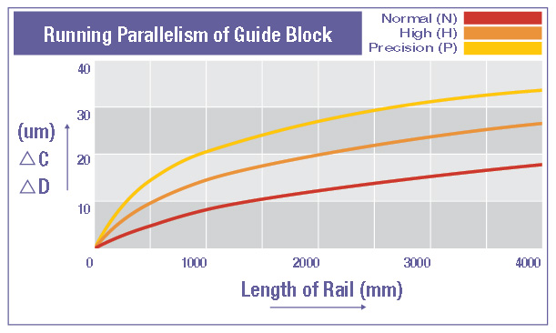
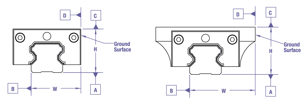
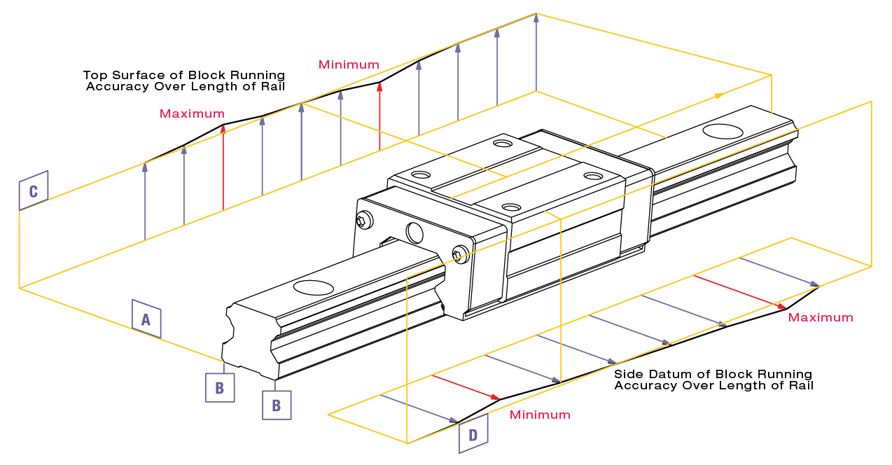
Running Parallelism
Running parallelism is defined as the deviation of parallelism between the reference datum surface of the guide block and the reference surface of the rail when the guide block is moving over the entire length of the rail.
RPG blocks have one qualified datum edge where as the rail edges are universal, meaning both edges of the rail are considered datum edges.
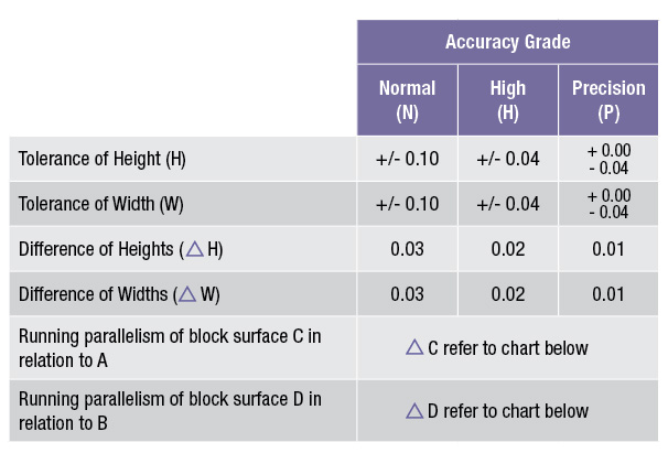
Difference in Height (ΔH)
By definition, difference in height is the maximum difference in height (H) measured between any pair of blocks on the same rail or set of rails mounted on the same plane.
Difference in Width (ΔW)
The maximum difference in width (W) between each block mounted on the same rail is known as the difference in width.
Note: The accuracy is measured at the center or central area
of the block.
Radial Clearance
Radial Clearance is defined as the vertical play between the block and rail as measured at the center of the block. The radial clearance is measured by lightly lifting up on the block.
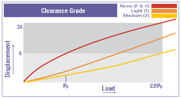
Preload
Preload is a precise mechanical load applied to the rolling elements (balls) in order to increase the systemic rigidity and eliminate radial clearance. Four way equal loading of RPG blocks resists normal, transverse, and moment loading. Mounting Accuracy may dictate the allowable Preload (See Tables 31A and 31B). The blocks are shipped with the specified preload and no further adjustment is necessary.
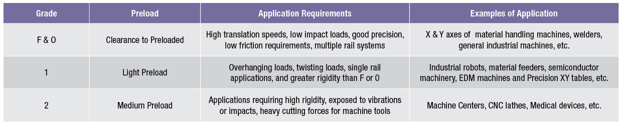
Rigidity
The rigidity of the guide assembly can be increased depending on the magnitude of the preload.

Friction
The frictional characteristics of rolling element guideway systems are substantially superior to those based on sliding element principles. In order to minimize frictional losses, the RPG product offering, as described in this catalog, has been designed with four rows of rolling elements.
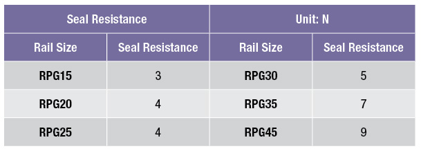
Although frictional losses in a linear guideway system are often minimal, they develop as a result of many variables such as differential ball slip, loading factors, lubrication viscosity, seal friction, and others. In general, the force required to overcome the frictional resistance of a linear guideway system can be calculated as follows:
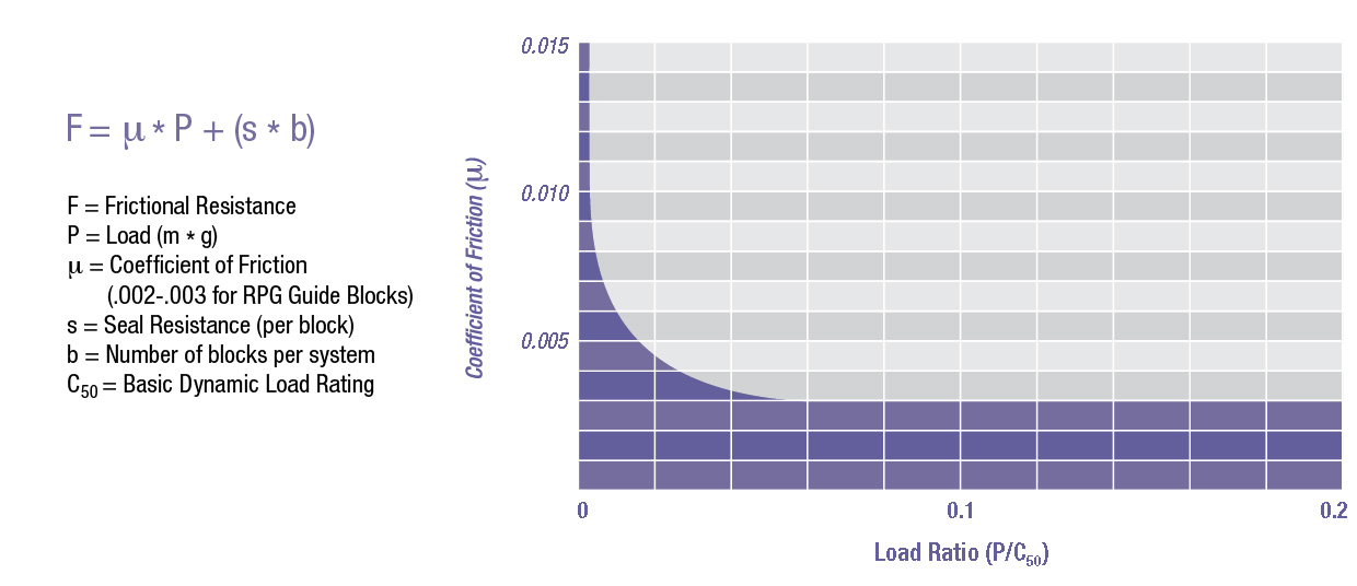
The stated seal resistance is based per block and assumes using the proper type and amount of lubricant.
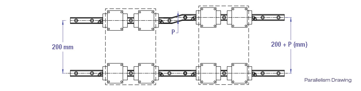
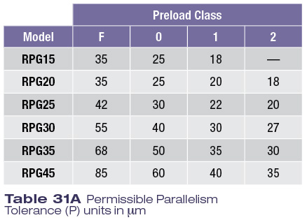
Permissible Tolerance for Parallelism of Two Rails
RPG Guides have self-aligning characteristics and therefore can accommodate some mounting surface errors while achieving smooth motion. The chart to the right indicates the maximum permissible tolerance specification for parallelism error (P) (based on preload selection).
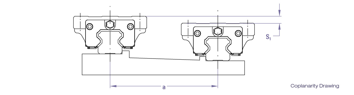
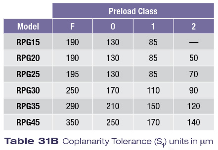
Permissible Tolerance for Coplanarity (two level offset) of Two Rails
The values for permissible coplanarity mismatch (S1) as shown below apply when the rail to rail distance is 500mm (Dim “a”). The permissible offset values are proportionate to the distance between the rails and therefore vary as the “a” dimension deviates from the 500mm.
Selecting the proper lubrication is critical to maximize the performance and the life of RPG guide assemblies. Therefore, the types of lubricant and lubrication methods should be carefully determined based on operating parameters and conditions.
All Rockford Linear Motion RPG blocks need to be lubricated with a NLGI Grade 2 bearing grease KP2K-20 to Din 51825. This is a high-performance lithium complex grease capable of operating at high speeds, heavy loads, and at temperatures beyond the limits of conventional lithium bearing greases. RLM recommends grease as the preferred lubricant unless speeds are in excess of 60 m/min, in which case oil should be used.
Note: Any selected lubricant must meet or exceed the stated factory bearing grease specifications.
When using oil as the lubricant, it is imperative to choose a product with the correct viscosity to meet the demands of the application (CLP; viscosities of ISO VG 32 to 680 per Din 51519). Oil mist lubrication systems can be utilized with a small positive pressure cavity to help keep the guide blocks clean. These misting systems will require oils with a viscosity that has high atomizing rates. The same factors that influence the choice of a grease should also be considered when choosing an oil; such as loading, speed, temperature, vibrations, humidity, and others.
Lubrication Procedure
For best lubrication dispersal, the block should be lubricated through the supplied lube port while the block is in motion. This will ensure circulation to all internal bearing surfaces. When a guide system is oriented vertically, the uppermost lubrication port should be utilized to ensure gravity assisted lubrication dispersal. Excessive lubrication will result in lubricant escaping through the block seals.
In the instance of short stroke assemblies (≤2x block length (L1)), the block should be lubricated from both ends to ensure adequate lubrication to the entire ball track.
Lubrication Interval
The Lubrication Interval is often times dependent on operational and environmental criteria such as loading, speed, stroke travel, and ambient conditions. Lubricating blocks with a lubrication reservoir 2-5 times at equal intervals during the calculated life of the guide block should be sufficient. Blocks that do not have a reservoir should be lubricated more frequently.
Environments
Special environments such as vacuums, clean rooms and the food industry will require specialized grease or oils. Please consult the factory for recommendations.
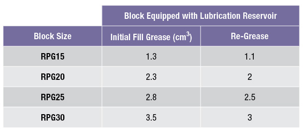
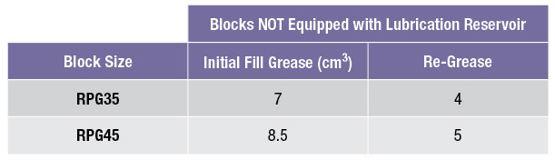
A Lubrication Reservoir is standard on RPG blocks sizes 15 through 30. The reservoir and block are not filled with grease at the factory and will need to be lubricated prior to operating. The amount of lubrication required is shown below:
Contamination due to dust and other foreign particulates can cause premature wear or failure to RPG guides. To protect the RPG guides, effective sealing or contamination protection measures should be carefully selected based on the operating environment.
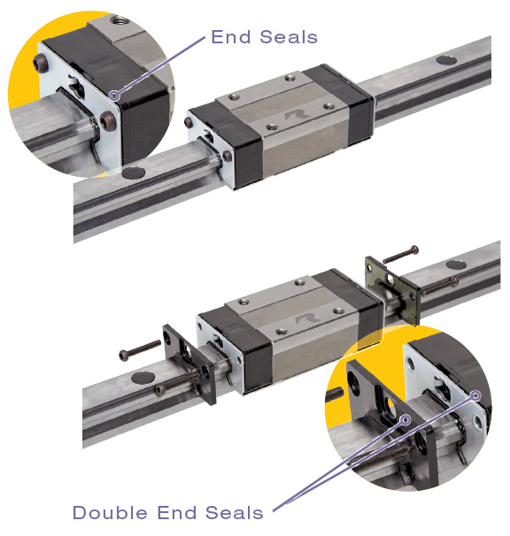
End Seals
End Seals made from synthetic rubber are designed to have anti-wear properties while providing bidirectional dust protection with little increase in frictional resistance.
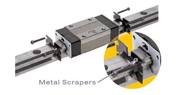
Metal Scrapers
Metal Scrapers are used for keeping larger particulates such as weld splatter, metal chips, and ice from entering the guide block.
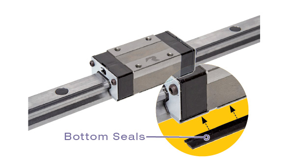
Bottom Seals
Bottom Seals are provided on all standard length RPG guide blocks and are designed to seal the underside of the block from contaminates.
Hole Cap Plugs
Hole Cap Plugs are included with all rail shipments. The plastic cap is designed to keep contaminates out of the rail bolt holes which could then migrate into the block.
Bellows
Bellows, or telescopic covers, may be required to keep out the most difficult contaminates such as machining chips and coolants.
Accessories Installation
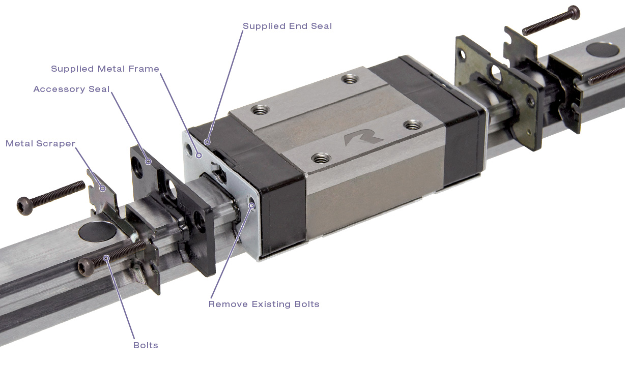
Note: The RPG Block(s) should be installed on the rail before proceeding with the accessory installation. Complete installation on one end of the block before beginning the other end.
- Remove the existing bolts from the end of the block assembly.
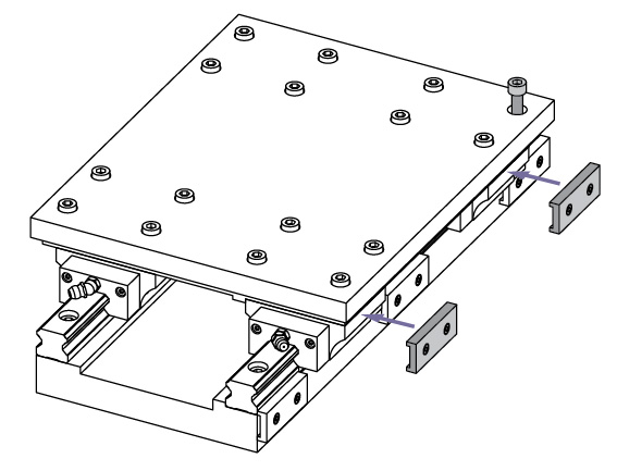
- Gently slide the accessories onto the rail and up against the block. Depending on the model, the additional accessories will either be installed flush to the existing end seal or the metal frame of the block. The scraper plate, if applicable, should always be mounted last.
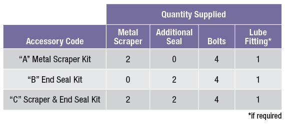
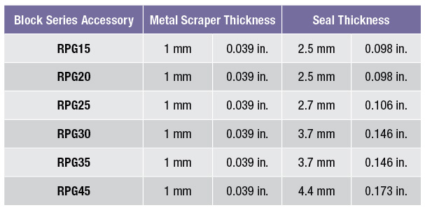
- Insert the proper bolts into the bolt holes of the block and tighten. Note: When additional end seals and/or scrapers are installed on the RPG blocks, the overall length (L dimension) will increase (See Table 35B for scraper and seal thickness). If required, a longer lube fitting and bolts will be provided with the accessory kit and should be used in place of the original. If an additional lube fitting and/or bolts are not supplied as part of the kit, the original parts should be used.
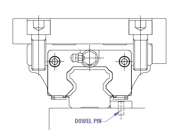
Fixing Methods
Methods TO positively LOCATE THE rail IN THE ABSENCE OF A datum surface on machine base
The most common arrangement for attaching the rail to a structure is one in which there is not a positive transverse locating surface. The location of the rail under load is maintained by the frictional resistance mounting created primarily by the Rail Mounting Bolt Torque. Therefore, in this instance, proper Bolt Torque is extremely important to maximize the frictional resistance and preclude rail displacement during transverse loading. As a more positive locating method, plates can be installed and dowel pinned in a fashion to more positively resist transverse loading.
Methods TO positively lock THE rail and blocks against datum surface
There are a number of methods to positively lock the rail and block datum surfaces. These methods will aid in maintaining rigidity and accuracy in applications where vibrations or impacts are present.
RPG Rails are manufactured to be interchangeable, meaning that both edges are datum surfaces. This forgoes having to know which side of the rail is the reference edge. The blocks however have only one datum edge which is the edge with a ground surface.
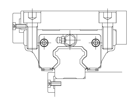
Push Plates
Push Plates can be used in multiple points along the edge of the rail or block, a single push plate may run the full length.
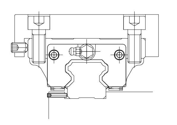
Push SCREWS
Push Screws can be utilized to hold the block & rail against the datum surface. Multiple screws should be spaced along the length of the rail or block.
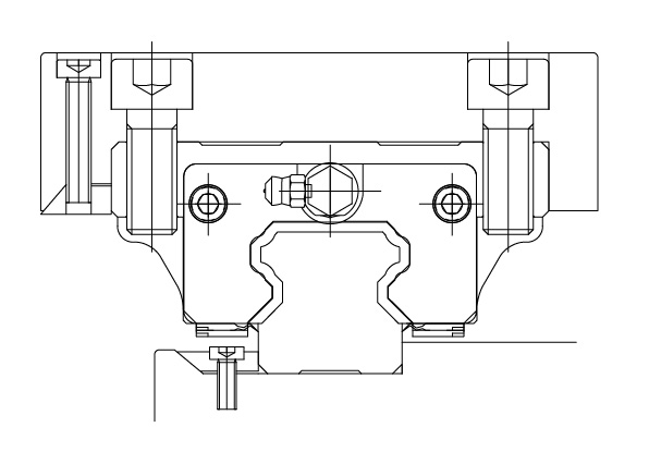
Tapered Gibbs
Tapered Gibbs can generate large pressing forces and can cause rail deformity. Therefore, this method should be used with caution.
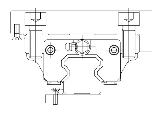
Needle Roller
Needle Roller loading is achieved by the taper of the screw head pressing on the needle roller. The location of the screw is extremely important in order to achieve proper loading on the needle.
Installation Procedure
RPG Guide Rails are manufactured to be interchangeable, meaning that either side of the rail can be used as a primary locating datum edge. When two or more rails are used in a parallel system, one of the rails is considered the master rail while all others are auxiliary. In a single rail installation there is only a master rail.
Installation Instructions for a Two Rail System with Positive Reference Edge & Normal Mounting Surfaces for the Master Rail
Grease Fittings and Accessories.
If block accessories, such as additional end seals and/or metal scrapers are not required, the grease fittings and lube port plugs should be assembled onto the blocks prior to installing the blocks on the rail. However if additional accessories are being used, please refer to the installation instructions on page 35 as some kits will require an alternative lube fitting.
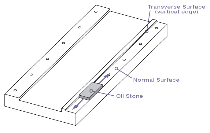
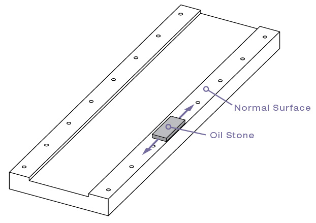
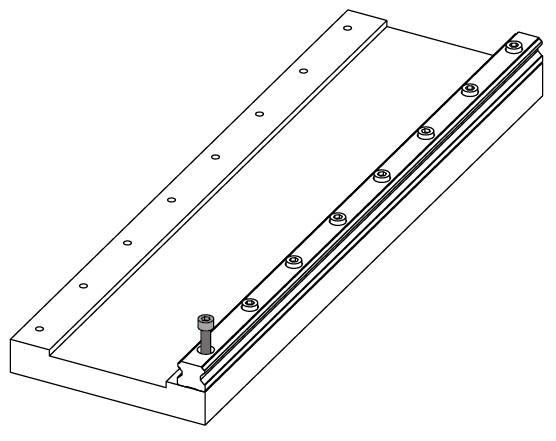
1 - The rail mounting surfaces need to be free of burrs, dirt, rust preventative oil, and foreign material before installation of the rails. Use an oil stone on the master and auxiliary rail mounting surfaces to remove any high spots or dislodge any foreign material that may exist.
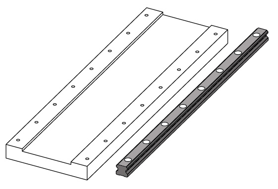
2 - Place the Master rail on the prepared rail mounting surface. It is recommended to install the block(s) at a later point in this procedure to avoid accidental block damage. However for applications where subsequent block installation is not possible, proper access to all of the rail mounting bolt holes should be checked and block end accessories installed as applicable.
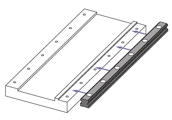
3 - While holding the rail against the datum edge, insert clean bolts, check for correct bolt fit, and lightly snug all bolts. The torque applied to the bolts during this step should allow for subsequent rail movement as may occur during installation of the push plates.
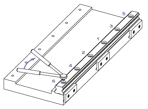
4 - Install and tighten the clamping mechanisms (Push Plates shown) in sequence starting from the middle of the rail and working towards the ends.
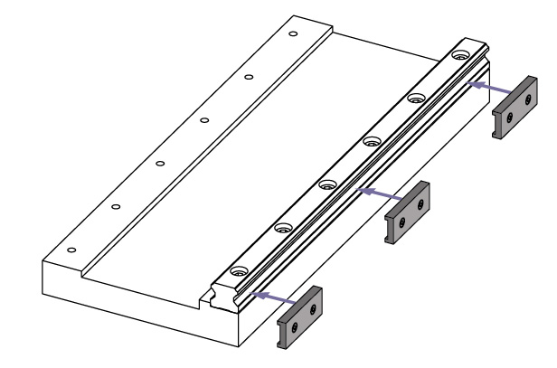
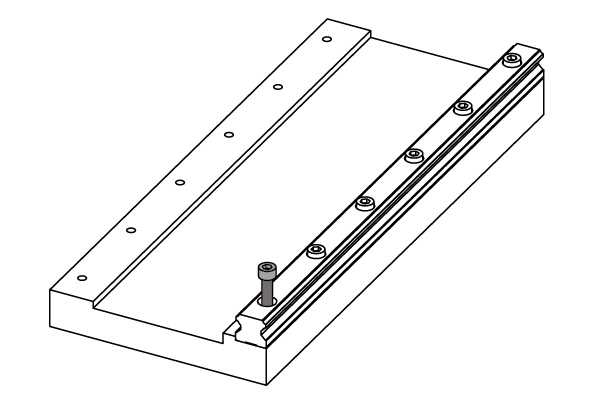
5 - Torque the rail mounting bolts to specification (as shown below) in sequence beginning with the bolts at the center of the rail and working towards each end as shown below. A torque wrench should be used to set the specified Bolt Torque.
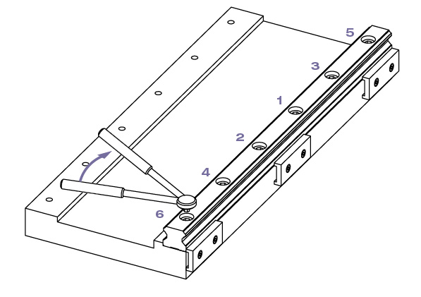
6 - The block(s) should now be installed on the master rail only. Be sure the end of the rail is free from burrs and all foreign materials prior to attempting installation. If a datum edge is being utilized on the component that assembles on the block(s), remember to install the block so the ground datum edge of the block faces towards the datum locating surface.
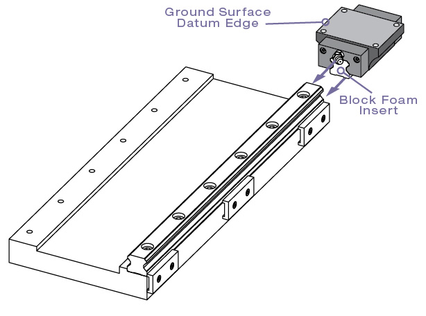
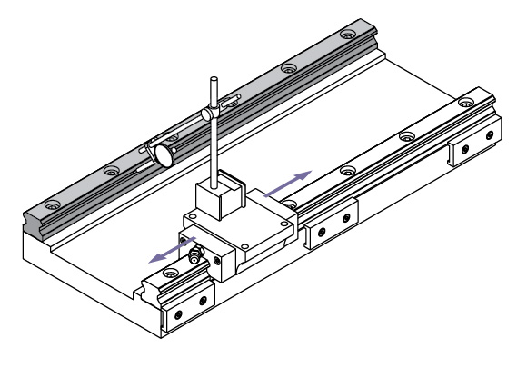
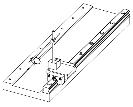
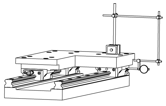
7 - Install a block and dial indicator on the master rail for alignment purposes. While displacing the block and indicator from one end of the master rail to the other and indicating relative to positive locating feature(s) of the device, verify the alignment of the rail assembly to the indicated locating features
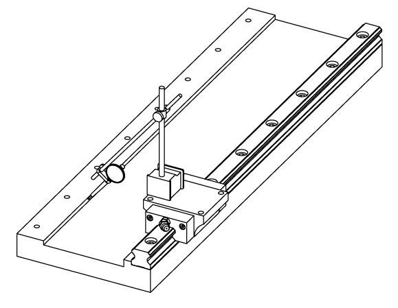
8 - Place the auxiliary rail on the prepared rail mounting surface, insert clean rail mounting bolts, and lightly snug the bolts in preparation for aligning the auxiliary rail to the master rail. Torque the bolts to the same standard as used in Step 3.
9 - Inspect the parallelism and height variation of the auxiliary rail relative to the master rail by using an indicator or other appropriate means. If necessary, the auxiliary rail should be gently re-positioned relative to the master rail within the noted variation limits.
10 - Torque the auxiliary rail mounting bolts to specification in sequence beginning with the bolts at the center of the rail and working towards each end (See Step 5). A torque wrench should be used to set the specified bolt torque. Once the bolts have been sequentially torqued, the alignment of the auxiliary rail to the master rail should be re-verified by using the procedure stated in Step 9.
11 - Install the cap plugs into the bolt hole counter bores as shown below.

12 - Install the remaining blocks on the master and auxiliary rails. Additional end seals and/or scraper kits should be assembled while the block is installed on the rail.
13 - Install the assembled component(s) that mount onto the blocks and lightly tighten the mounting bolts. If push plates are being used, they should be installed and their mounting bolts tightened to secure positive location of the block datum surface to the mating component datum surface.
14 - Sequentially torque the assembled component(s) mounting bolts starting with Block #1 and finishing with Block #4. The linear guidance system should be checked for smooth operation along the entire travel. If any binding or excessive resistance is encountered, the alignments as shown in Step 9 should be re-verified.
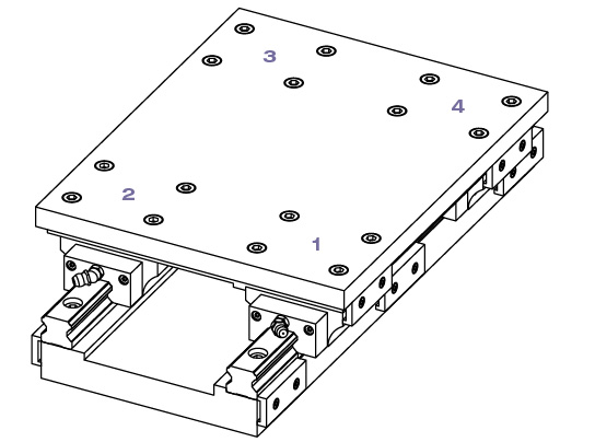
15 - As a final measure, the initial charge of lubricant should be introduced into each block as recommended.
Installation of a Rail System Without a Positive Reference Edge Locating Surface
Grease Fittings and Accessories.
If block accessories, such as additional end seals and metal scrapers are not required, the grease fittings and lube port plugs should be assembled onto the blocks prior to installing the blocks on the rail. However if additional accessories are being used, please refer to the accessory installation instructions as some kits will require an alternative lube fitting.
1 - The rail mounting surfaces need to be free of burrs, dirt, rust preventative oil, and foreign material before installation of the rails. Use an oil stone on the master and auxiliary rail mounting surfaces to remove any high spots or dislodge any foreign material that may exist.
2 - Place the Master rail on the prepared rail mounting surface. It is recommended to install the block(s) at a later point in this procedure to avoid accidental block damage. However for applications where subsequent block installation is not possible, proper access to all of the rail mounting bolt holes should be checked and block end accessories installed as applicable. Refer to Step 12 for end accessory installation instructions.
3 - Insert clean bolts, check for correct bolt fit, and lightly snug all bolts. The torque applied to the bolts during this step should allow for subsequent rail adjustment as may be necessary during the following alignment procedures.
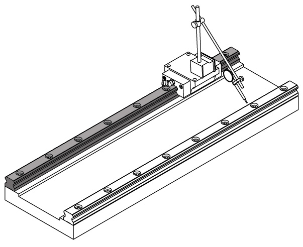
4 - While keeping the block datum edge in proper orientation, install a block and dial indicator on the master rail for alignment purposes. While displacing the block and indicator from one end of the master rail to the other and indicating relative to positive locating feature(s) of the device, gently re-position the rail into proper alignment. An example of this alignment procedure is shown in Step 7. Reference Step 6 for block installation.
5 - Torque the rail mounting bolts to specification in sequence beginning with the bolts at the center of the rail and working towards each end. A torque wrench should be used to set the specified bolt torque. Once the bolts have been sequentially torqued, the alignment of the master rail should be re-verified by using the procedure stated in Step 4.
6 - Place the auxiliary rail on the prepared rail mounting surface, insert clean rail mounting bolts, and lightly snug the bolts in preparation for aligning the auxiliary rail to the master rail. Torque the bolts to the same standard as used in Step 3.
7 - Inspect the parallelism and height variation of the auxiliary rail relative to the master rail by using an indicator or other appropriate means. If necessary, the auxiliary rail should be gently repositioned relative to the master rail within the noted variation limits.
8 - Torque the auxiliary rail mounting bolts to specification in sequence beginning with the bolts at the center of the rail and working towards each end (Step 5). A torque wrench should be used to set the specified bolt torque. Once the bolts have been sequentially torqued, the alignment of the auxiliary rail relative to the master rail should be re-verified by using the procedure stated in Step 7.
9 - Install the cap plugs into the bolt hole counter bores as shown below.
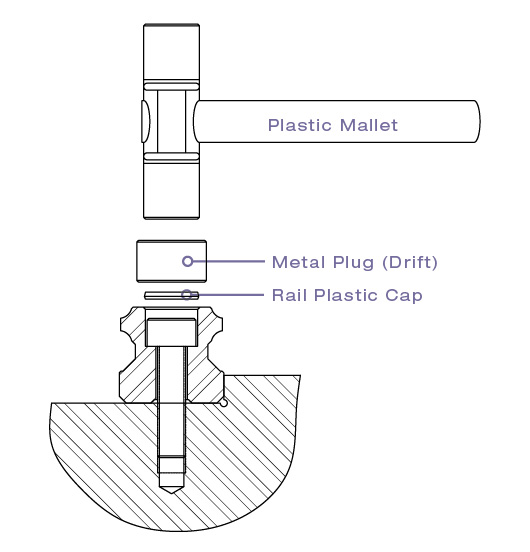
10 - Install the remaining blocks on the master and auxiliary rails. Additional end seals and/or scraper kits should be assembled while the block is installed on the rail as shown (reference accessory installation instructions).
11 - The assembled components mounting to the blocks should be installed and aligned to the linear guidance system. Once these alignments are completed, the linear guidance system should be checked for smooth operation along the entire travel. If any binding or excessive resistance is encountered, the alignments as shown in Step 7 should be re-verified.
12 - As a final measure, the initial charge of lubricant should be introduced into each block as recommended.