
Ball Nuts
Rockford Ball Screw stocks several dozen sizes and configurations of inch ball nut assemblies including standard, preloaded and keyway designs. We can easily modify our ball nuts by adding special mounting threads such as UNJ or metric, trunnion mounts, flanges and/or adaptors to interface with your design. In addition, we can make fully custom ball nuts to meet your design requirements as well as work with specialty materials, special heat treatments and different coatings (i.e. Armoloy, Nickel, Chrome, Zinc, PTFE, Phosphate, etc.) all to meet your requirements.
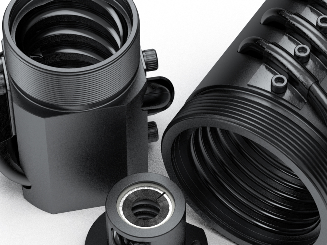
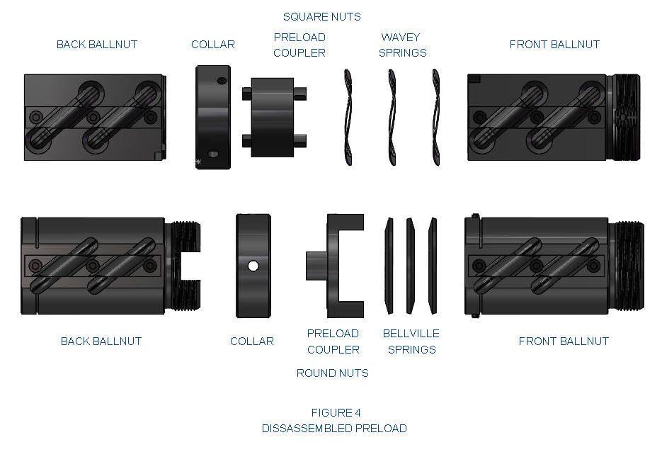
For applications requiring no backlash and positioning accuracy, our inch preloaded ball screw assemblies are the best solution. The preloaded ball nut assembly design consists of two standard ball nuts joined by an adjustable preload package containing a collar and bevel, or wave springs (see Fig 4 below). As a method of eliminating backlash in a ball screw assembly, preloaded assemblies work one group of ball grooves in opposition to another. Preloaded assemblies increase stiffness and provide for accurate positionings with very little increase in applied torque or decrease in load capacity.
Definitions & Formulas
Preloading & Backlash
A ball bearing screw is just that: a screw which runs on ball bearings. The screw and nut have matching helical grooves or races, and the ball bearings recirculate in these races. There is no physical contact between the screw and the nut. As the screw or nut rotates, and the rolling balls reach the trailing end of the nut, they are deflected or guided from this “pitch” contact by means of a return tube and returned to the leading end of the circuit. There, the cycle resumes and the balls recirculate continuously.
Major Diameter
(Land Diameter) The outside diameter of the screw thread.
Minor Diameter
(Root Diameter) The diameter of the screw shaft as measured at the bottom of the ball thread track. This diameter is used in column load and critical speed calculations. Minor diameter also is a consideration in support bearing selection.
Ball Pitch Diameter
(Ball Circle Diameter) The theoretical cylinder passing through the center of the balls when they are in contact with the ball screw and ball nut races.
Lead
The axial distance the screw or nut travels in one revolution.
Lead Error (Accuracy)
The difference between the actual distance traveled compared to the theoretical travel based on the lead of the screw. The lead error for a standard screw will not exceed +/-.007” per foot and a premium grade screw will not exceed +/-.003” per foot. Lead error is cumulative based on the actual length of the ball screw thread. Ref. Class 7-8 ANSI B5.48-1977. Lead charts describing incremental lead deviation offsets can be supplied (upon request). These incremental offsets can be input into motion controllers for lead error compensation.
Matched Leads
(Synchronous Screws) Used when multiple screws are being driven by a single drive in order to keep the screws in sync. Basically the lead errors are matched at the factory in order to minimize misalignments during the stroke. Consult factory for additional information on matched leads.
Pitch
The distance from one thread on the screw to a corresponding point on the next thread parallel to the screw axis. Pitch is equal to the lead on single start screws.
Screw Starts
The number of independent threads on the screw shaft. The lead of the screw is calculated by dividing the threads per inch by the number of starts.
Backlash
The axial free motion between the nut and the screw. It determines the amount of lost motion between the nut and screw on a horizontal application. Backlash on standard nuts range from .005 to .015, depending on the size of the screw.
Selective Fit
The process of selecting a unique ball size for reducing backlash to as little as .001 inches.
Preloading
Method of eliminating backlash in a ball screw assembly. This is accomplished by the use of one group of ball grooves in opposition to another to eliminate backlash. Preloading increases stiffness (resistance to deflection) and provides for accurate positioning with very little increase in applied torque or decrease in load capacity.
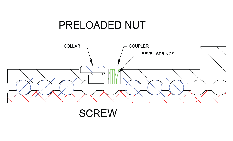
Rockford Ball Screw preloaded ball screw assemblies consist of two standard ball nuts joined by an adjustable preload package containing a collar, coupler and bevel or wave springs. The preload package has been designed to exert an axial separating force between the adjacent ball nuts thereby generating the requisite preload. Preloaded ball screw assemblies are required when positioning accuracy and repeatability must be maintained.
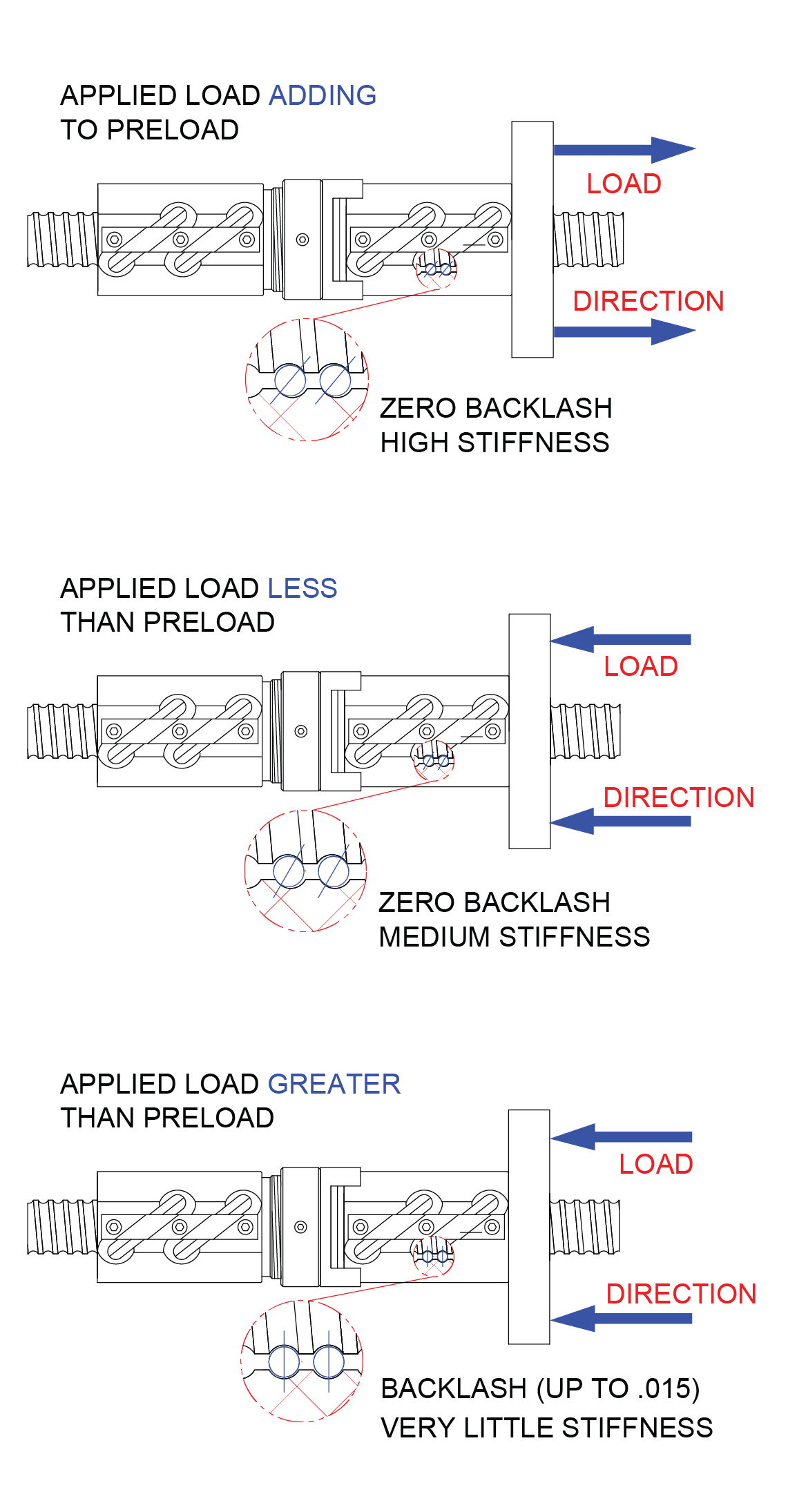
The adjustable preload can be set in a range between 10% (recommended) and 30% (maximum) of the dynamic load rating. While staying within this range, the assemblies demonstrate little loss of load carrying capacity or life.
The three preload examples below illustrate the effects of load size and direction on preloaded units. The examples are important in selecting the size of preload and amount of preload force needed. The direction of loading effects ball screw stiffness and potential backlash.
Loading
Efficiency
Expressed as a percentage and is the ability of a ball screw assembly to convert torque to thrust with minimal mechanical loss. Rockford Ball Screws operate in excess of 90% efficiency.
Dynamic Load
The maximum thrust load under which a ball screw assembly will achieve a minimum of 1,000,000 inches of travel before first signs of fatigue are present.
Static Load
The maximum non-operating load capacity above which permanent damage of the ball track occurs.
Tension Load
A load that tends to stretch the ball screw. This is the preferred mode of attaching the load since column loading limitations would not effect the screw.
Compression Load
A load which would tend to compress or buckle the screw shaft. Use column load calculations to determine safe compression loads.
Axial Loading
The recommended method of attaching the load to the ballnut. This load should be parallel to the centerline of the screw shaft and equally distributed around the mounting surface.
Eccentric
(Moment Loading) A load tending to cock the ballnut on the screw and therefore reducing the rated life.
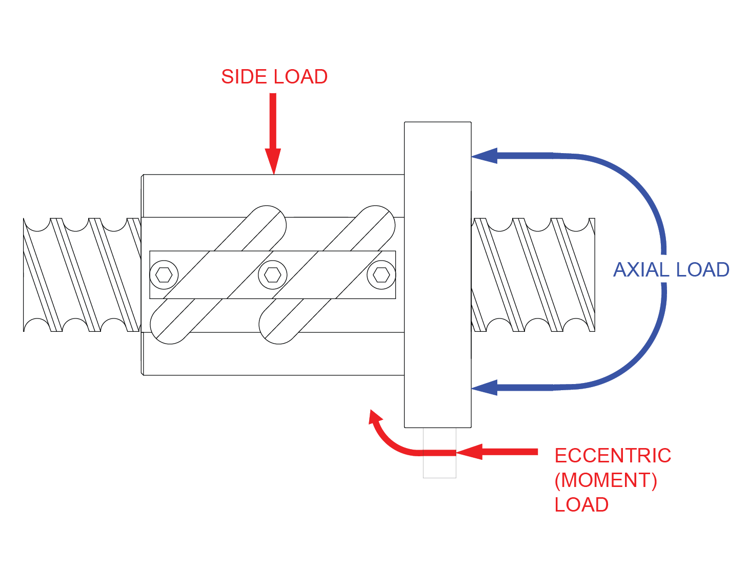
Side Loading (Radial Loading)
A load that is applied perpendicular to the screw shaft. This type of loading will also reduce the rated life of the ball screw assembly.
Ball Screw Life
(Life Expectancy) Expressed as total accumulated inches of travel under a constant rated thrust load (with proper lubrication and clean environment) before first evidence of fatigue develops (1,000,000 inches under stated rated loads). Ball screw life is rated similar to ball bearings (L10). The L10 life rating states that 90% of a similar group of screws will achieve this life. Although 10% will not achieve the life, 50% could exceed life by 5 times.
Applied Dynamic Loading
Each unique application needs to be evaluated such that ALL force components are realized and accounted for. The force components might include: weight of the sliding mechanism (if vertical), weight of the sliding mechanism multiplied by the coefficient of sliding friction (if horizontal), any direct forces resisting the linear motion (such as tool cutting loads), and any other applicable force components.
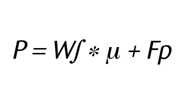
P = Applied Dynamic Load (LBS)
W∫ = Weight of Sliding Load (LBS)
µ = Coefficient of sliding friction
(=1 if load orientation is vertical)
Fp = Force component pushing directly against
the sliding mechanism
Coefficient of sliding friction for non-vertical loading applications
Steel on Steel ~.58
Steel on Steel (greased) ~.15
Aluminum on Steel ~.45
Gibb Ways ~.50
Dove Tail Slides ~.20
Linear Bearing (Ball Bushings) <.001
Frictional coefficients are included for reference purposes only and may vary in accordance with actual operating conditions.
Equivalent Load
This calculation is used in applications where the load is not constant throughout the entire stroke. This equivalent load can be used in life calculations. In cases where there is only minor variation in loading, use greatest load for conservative life calculation. Please note that the drive torques and horsepower requirements should always be based on the greatest thrust load encountered.
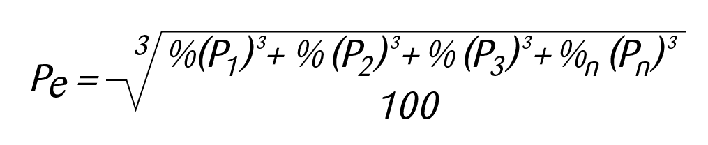
Pe = Equivalent Load (lbs)
Pn = Each Increment at Different Load (lbs)
%n = Percentage of stroke at load increment
Example:450 lb. load for 25% of stroke
760 lb. load for 50% of stroke
200 lb. load for 25% of stroke
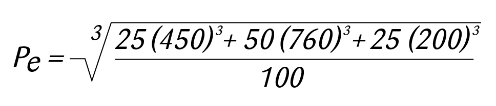
Equivalent Load (Pe) = 625 lbs.
Life At Loads
(Other than Rated) Based on the inverse cube ratio in that by operating at 1/2 the rated load you will get 8 times the life or operating at twice the rated load you will get 1/8 the life.

Design Life Objective
Design Life Objective is the number of inches that a ball screw will travel during the desired life of the machine. Generally it is ultimately stated in terms of years of life but we need to compare inches of travel to inches of calculated life.
Length of stroke = 6 inches
Cycle rate of machine = 20 Strokes/hr.
Hours of operation /day = 16 hours
Number of working days per year = 250 days
Number of years machine is designed for = 5 years
6 * 20 * 16 * 250 * 5 = 2,400,000 inches of life
Mounting & Wiper Kits
Wiper Kits
Wiper kits are available for all standard ball screw models. The nylon brush wiper is designed to keep large particulates from entering the ball nut. However for harsh environments, the use of boots or bellows to enclose the screw is recommended. Contact Rockford Ball Screw for further information on enclosures.
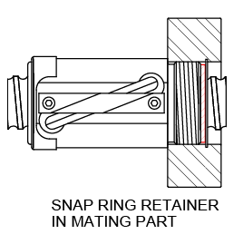
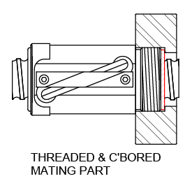
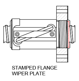
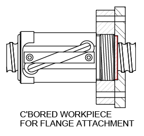
Our product pages detail the type of wiper mounting arrangement for each ball nut model. Brush wipers may require customer supplied retention primarily on the V-thread end of the ball nut (on models that do not have internal wipers and snap rings). A stamped flange retainer is available for many models that do not have internal snap rings for wiper retention (see data pages for available sizes).
Mounting Flanges
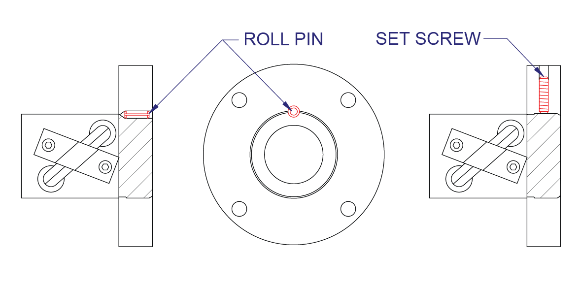
If a mounting flange is used instead of the standard v-thread on the ball nut body, it must be permanently attached to prevent disengagement during operation. The two standard methods of retaining the flange is pinning and retaining with a set screw. Commercial thread locking adhesives may also be used (light loads only). It is always recommended that the flange pinning be performed at the factory to assure no metal chips are present after drilling.
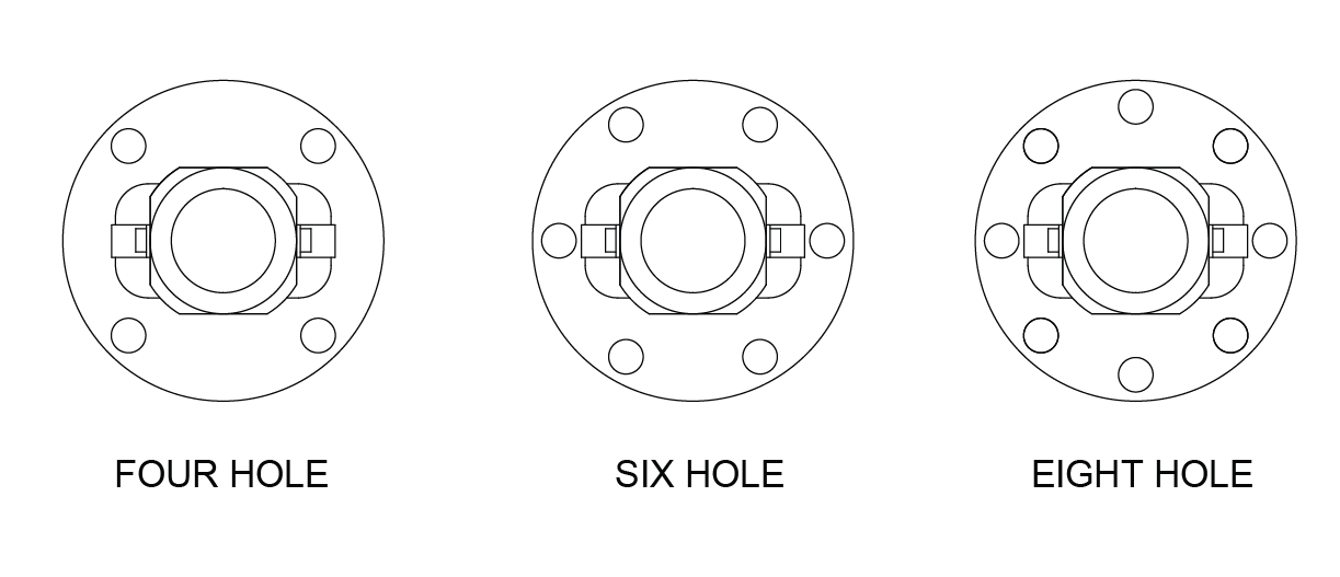
Flange Orientation
The orientation of the flange bolt holes to the return tube components varies with the number of holes in the flange. Unless otherwise specified, the following illustrations represent the standard orientations.
Lubrication
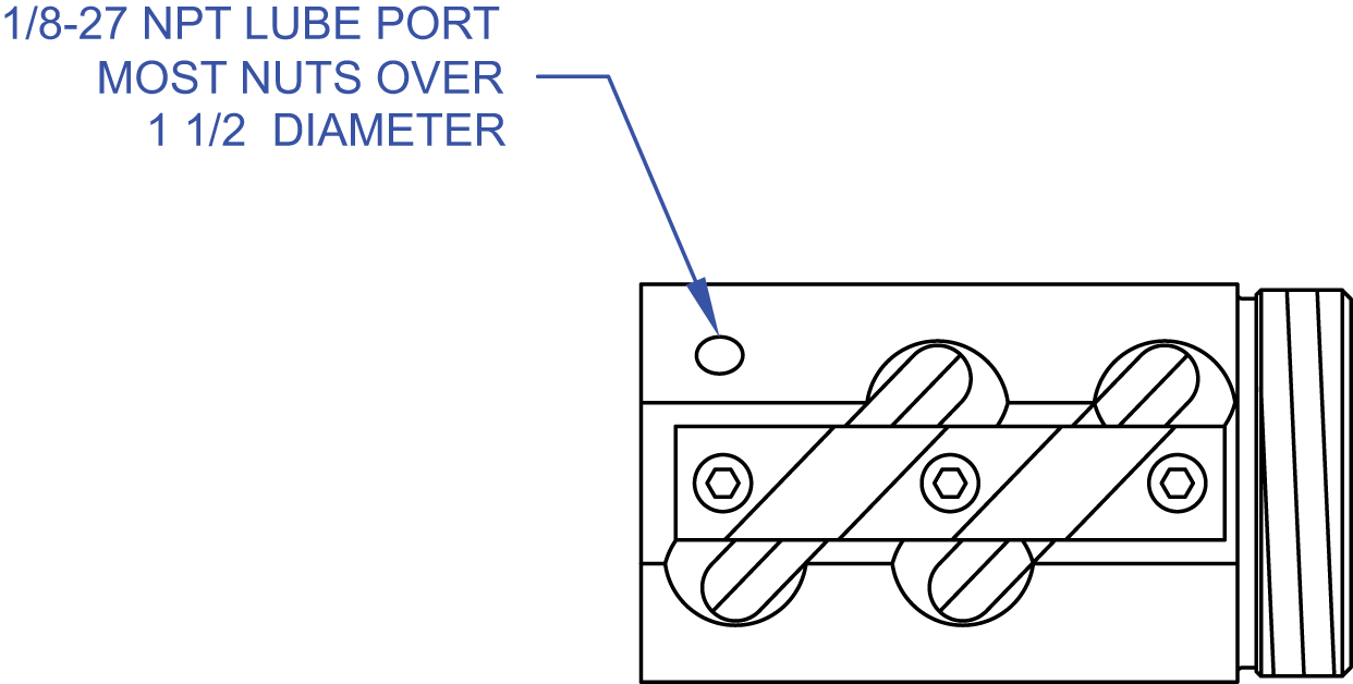
Lubrication is required to achieve optimum life for a ball screw assembly. Ball screws that are not lubricated can experience up to a 90% reduction in calculated life. In general, standard lubrication practices for anti-friction rolling element bearings apply. Grease, oil or dry film lubrication can be used. Many ball nuts are equipped with a 1/8-27NPT lube port machined into the nut body. For models that do not have a factory lube port, contact factory for recommendations regarding application of lubrication.
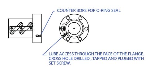
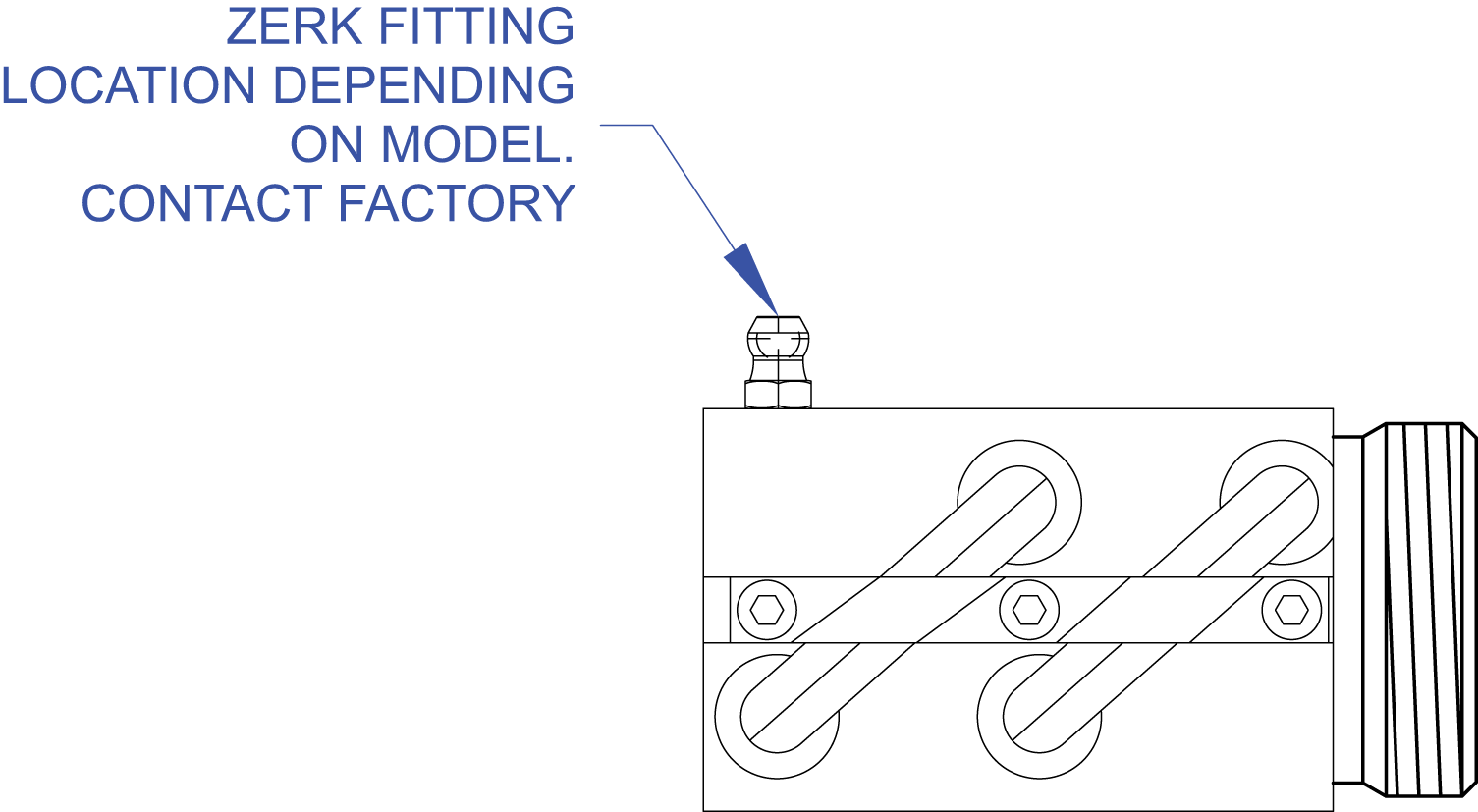
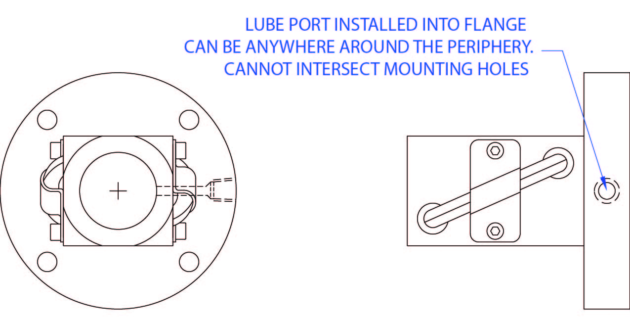
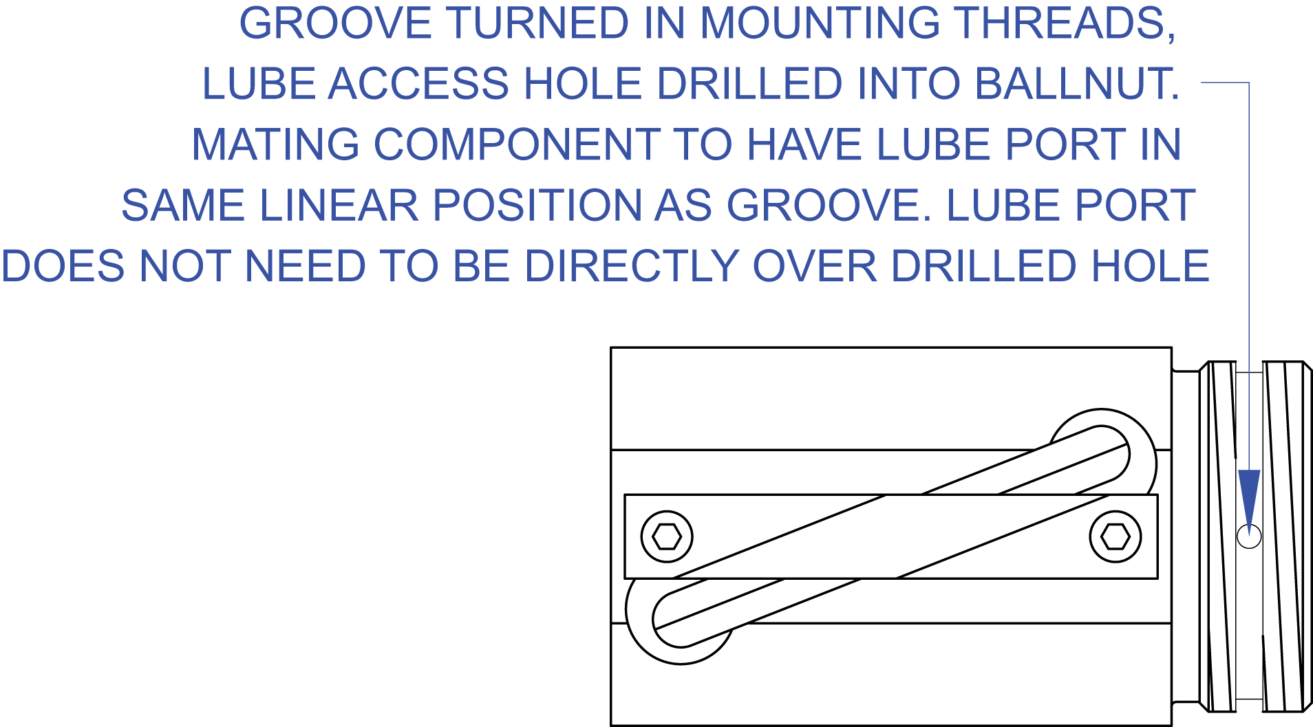
Lubrication of the ball screw assembly is extremely important to maintaining optimum efficiency and life. The ideal access point of introducing the lubrication is directly into the ballnut. Below we have illustrated a number of methods that have been utilized to ease the process of lubricating the ballnut. Should none of the methods apply to your application, please consult factory.
LUBE PORT INCLUDED ON BALLNUT
LUBE PORT IN FACE OF FLANGE
ZERK FITTING INSTALLED IN SIDE OF NUT
LUBE PORT INSTALLED IN FLANGE
LUBE ACCESS HOLE IN GROOVE OF MOUNTING THREAD
RBS Multi-purpose Synthetic Grease
AVAILABLE IN 14 OZ. CARTRIDGES
NOTE: To achieve optimal grease performance, it is recommended that the machine components should be kept in careful alignment, the operating environment should be kept clean, and the assembly should be periodically inspected for proper lubrication quantity and integrity.
Advantages
Proper lubrication along with reducing/eliminating foreign contamination are essential for preventing premature catastrophic failure. The R/B/S multi-purpose PTFE fortified synthetic grease has been specifically formulated with extreme pressure and anti-wear additives to reduce rolling element friction, wear, and provide noise damping characteristics. The excellent mechanical stability allows for compatibility with ferrous metals, non-ferrous metals, and most engineering plastics.
Consult the factory for specific material interactions. R/B/S recommends this grease be used for ballscrew, ACME screws, bearing mount, and other applications requiring excellent hydrodynamic lubrication.
Data Multi-Purpose Grease Specifications:
| NLGI Grade: | 2 |
| Temperature Range: | -40ºF(-40ºC) to 300ºF(135ºC) |
| Base Fluid Viscosity (cSt): | 75 @ 40ºC 12 @ 100ºC |
| Worked Penetration: (ASTM D1403) | 291 |