How to specify, install and maintain linear guide rail systems for factory automation

Article appears in Engineering 360:
https://insights.globalspec.com/article/16156/how-to-specify-install-and-maintain-linear-guide-rail-systems-for-factory-automationIn automation cells, precise, repeatable and long-lasting linear motion is critical. The Rockford Linear Motion (RLM) product line from Rockford Ball Screw (RBS) offers linear guide rail systems that are manufactured to extremely tight tolerances. With multiple accuracy grades available, they can meet many demands and requirements, allowing customers to have years of problem-free operation. As with any component subject to the continuous rigors of industrial operation, guide rail systems must be properly specified and installed, then maintained once in use. This might seem overwhelming at first, but with some basic information and common design practices, the right guide for the application can be found.
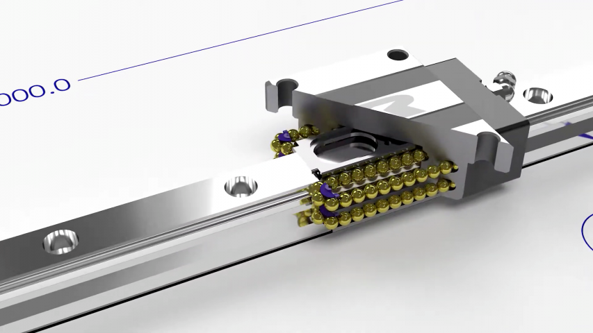
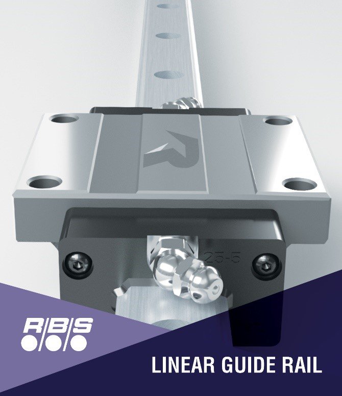
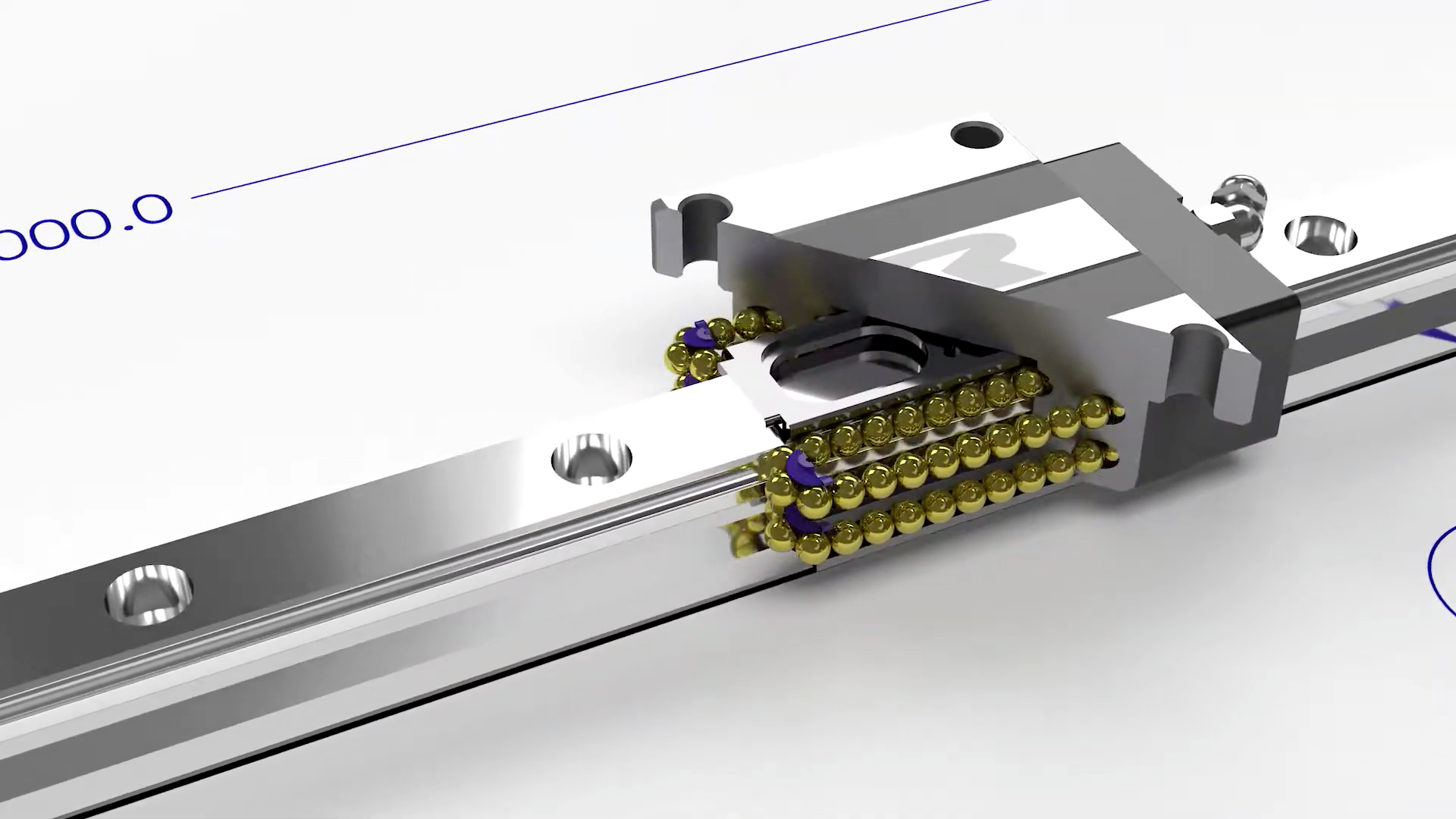
Like most linear guides, RLM offers four recirculating bearing contact surfaces for smooth travel and controlled linear motion. They are available in a wide range of size and load capacities. But most guide systems have many different rails for different options. Some could have four to five different rails for the same nominal size. This makes it difficult for designers, and to replace or interchange the units after they have been installed. The RLM brand RPG guide series features a single common rail for all block options for a given size. This simplifies the design effort and gives designers a lot of flexibility to quickly change features depending on applications or changes in scope. The RPG guide series are available in a wide range of sizes and load capacities to meet almost every application requirement. Designers can also add multiple blocks to a given rail for additional load capacity and add multiple guide rails in series for long-travel applications.

Figure 1. Linear guide rail.
Specifying
When choosing from available guide rail options, the driving factor will normally be the expected service travel life under a given load condition. This is nominally specified as the dynamic load rating, or C50, defined as the constant amount of downward force that can be applied at the center of the guide block while in constant motion to achieve 50 km of linear travel with 90% reliability (i.e., L10 life).
However, rarely is an application so straight forward as having a single load centered over the guide block traveling at a constant speed. Loads are offset, causing moments and changes in value and travel profile. Guide rail systems can be installed vertically, upside down and on their sides. Controller motion profiles such as accelerations and decelerations and ‘jerk’ values also can impact the load capacities. The more detail that is available, the more accurate the calculations.
The RLM Catalog (as found on the RBS website) includes helpful calculations, tips and examples to help make things easier on the designer to work through and select the right bearing. This level of detail and calculations can be intimidating. Start with the worst-case forces and moments and factor of safety. If the life is less than 50 km, then the catalog values will enable users to get very close to the right size linear guide system. Using the additional data to determine load profiles over life, the user can calculate equivalent loads that can help to narrow down the nominal size and perhaps go to a smaller size guide system. RBS factory support personnel are available to help with this process.
Installation
Once guide rails and the block are sized and selected, proper installation on a good solid foundation must then be executed to allow for optimum performance. The RLM catalog makes it easy for designers to determine the required tolerances on flatness, straightness and parallelism quickly and easily. The RPG series linear guides offer many advantages, such as stiffness, better wipers and lubrication reservoir option. But more significantly the RPG series linear rails feature datum edges on both sides of the rail to relieve concerns over installing it backwards and having to spend time documenting the orientation on drawings, work instructions and inspection sheets.

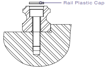
Figure 2. Plastic caps help prevent contamination.
The guide rails are generally pushed against a datum (or shoulder) to help ensure straightness and then bolted down. Plastic caps can be installed over the bolt head and flush with the top of the rail to help prevent contamination. When two rails are installed parallel to each other, it is recommended that the primary side be installed against a datum and the secondary side ‘float’ and then aligned to the primary side. Proper bolt torque will help ensure that the rails do not move. Dowel pins can also be used to help facilitate proper positioning. To help ensure that the guide rail is against the datum reference, clamps or push screws can be used to push the guide rail against the datum. Care must be taken not to overtighten these so that they do not deform or damage the guide rail. Once installed, the guide rail(s) should be verified with an indicator to ensure straightness or parallelism for smooth operation.
The guide blocks should be added to the rail(s) with end seals or scraper kits as specified. If installing parallel guide rails, the carriage should be installed on the primary side carriages first by use of a datum or shoulder (like the guide rails) to push the carriage against the primary side guide blocks. Then the carriage can be secured to the secondary guide blocks. If applicable, the carriage can have slotted holes to help overcome some misalignment or tolerance stack up.
Maintenance

Figure 3. Once the guide blocks have been properly installed, an initial charge of lubricant should be added, as they are not lubricated from the factory.
RBS recommends a high performance NLGI Grade 2 bearing grease KP2K-20, specified to DIN 51825 for the majority of applications. For speeds in excess of 60 m/min, however, oil should be used. The designer should consider the overall system and environment, such as the proximity of incompatible grease or excessive temperatures. Special environments, such as vacuum chambers, food processing facilities and clean rooms will require lubricants specialized to these conditions.
When in operation, lubrication will need to be added to guide blocks with reservoirs between two to five times during its calculated life. Guide blocks that do not have a reservoir will need more frequent lubrication.
